


INSTALLATION-PERIPHERALS
SECTION lOO-816-207
MARCH1993
l
Data Terminal Ready (DTR, Pin 20): The DTE
device sends the DTR signal (EIA circuit CD) to
the DCE device, prompting the DCE device to
open the communication line. The line is closed
and the call disconnected when the DTE device
quits sending the DTR signal. DTR may be sent
any time to indicate that the DTE is ready to
transmit or receive data. DIP switch SW1 -2 should
be set OFF in most cases (see Figure 7-32 for DIP
switch information).
l
Ring Indicator (RI, Pin 22): The RI signal (EIA
circuit CE) is sent by the DCE device to the DTE
device. Whenever the DCE device receives a
ringing signal on the line side, it turns the RI signal
ON. If DIU DIP switch SWl-3 is set ON, the RI
signal will be on continuously if ringing; if the
switch is set OFF, the RI signal will be one second
ON/three seconds OFF when the DIU detects
ringing signal.
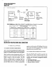
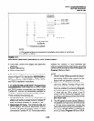
10.30 DIP Switch Options
10.31 The PDIU-DI and the PDIU-DS each have a
four-control DIP switch which can be configured for
signaling options. The switch is located on the
bottom of the PDIU-DI, and on the back panel of the
PDIU-DS (see Figure 7-32).
l
SW1 -1: Normally this switch is set ON to discon-
nect devices from DlUs automatically. The con-
nection is maintained if data is exchanged be-
tween the device and the DIU within eight to nine
second intervals. If SWl-1 is OFF on the called
and calling DIU, data calls will remain connected
until released manually.
l
SWl-2: This switch is placed in the ON position
when the PDIU-DI (or PDIU-DS configured like a
DCE) must hold DCD and DSR ON continuously.
If SWl-2 is OFF, DSR follows DTR and DCD will
be ON only when the DIU is connected on a data
call to another DIU. SWl-2 should be OFF on a
DIU when it is connected to a personal computer
that uses a communications software program to
establish data calls with AT commands; and
whenever PDIU-DS is connected to a modem.
l
SWl-3: The PDIU-DI (or PDIU-DS configured as
a DCE) sends the Ring Indicate (RI) signal to the
computer to tell the computer (DTE) that the PDIU
is receiving an incoming call. SWI-3should be ON
for the DIU to send RI steady, and OFF to send at
one second ON/three seconds OFF intervals.
l
SWl-4: This switch is placed in the ON position if
the computer does not output the RTS signal or
when connected to a modem that tracks the DCD
signal (modem set with AT&Cl). Sometimes, the
DTE device may use RTS/CTS for Ready/Busy
flow control, in these cases SW1 -4 should be OFF.
In this case the DCD signal of the calling DTE is
used as the RTS lead of the called DTE and the
DCD signal of the called DTE is used as the RTS
signal of the other DTE. In this case a signal which
stops the DTE from transmitting data (usually the
CTS lead) should be cross-connected to the DIU’s
DCD signal. Consult the DTE device or applica-
tion software documentation to determine which
type of flow control is required. If the DIU-DS is
connected to a modem that tracks carrier detect
(AT&Cl) SWl-4 should be ON.
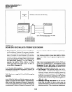
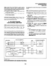
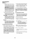
10.40 PDIU-DI to Personal Computer (PC)
Installation
10.41 The PDIU-DI always functions as a DCE
device; it transmits data on the Receive Data lead
(RD) and receives data on the Transmit Data lead
(TD). Most personal computers function as a DTE
device; PCs transmit data on the TD lead and
receive data on the RD lead. Follow the steps below
to install the PDIU-DI to a DTE, PC:
NOTES:
1. Use the steps below when installing an
ASCII terminal, personal computer, orany
other DTE device to a PDIU-DI.
2. The PDIU-DI can connect to a DCE com-
puter or any other DCE-type device using
a specially configured K-232 cab/e or
adapter; but this application is rarely re-
quired.
3. Change the PDIU-DI escape sequence
per the guidelines in paragraph 10.63.
1) Install the digital telephone that is to be
equipped with PDIU-DI per the instructions in
Section 100-816-206 and the drawing in Sec-
tion 100-816-208.
2) Install the PDIU-DI under the digital telephone
per the instructions in Section 100-816-206.
7-36