


3.10 DK8 KSU and DK16 Base Unit Relay
3.11 The DK8 KSU or DKI 6 Base Unit Relay can be
programmed for one of three options:
l
BGM mute
l
Night transfer
l
MOH source control
These options are set in Program 77-l (LED 01
and 02). Only one option is allowed per installation.
However, in the DK16, these options can be
supplemented with PIOU/PIOUS relay options.
Refer to Chapter 8 for wiring/interconnecting de-
tails. Electrical specifications for the relay contacts
are as follows:
Voltage
l
24VDC maximum
Current
l
1 ampere maximum
l
Normally open-closed when activated
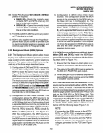
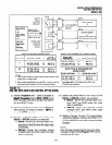
3.20 DK16 Expansion Unit PIOU and PIOUS
Relays
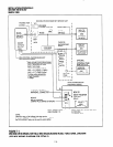
3.21 The Expansion Unit via the PIOU or PIOUS
provides two additional relays that control periph-
eral options (see Figures 7-6,7-7,8-23, and 8-25).
l
Door Lock Relay/BGM mute
l
Night Transfer/Music-on-Hold Relay
NOTE:
The above relay options are available in con-
junction with the Base Unit relay option.
3.22 Each relay may be configured as normally
open (make) or normally closed (BREAK). Electri-
cal specifications for the relay contacts are as
follows:
Voltage
l
24VDC maximum
Current
l
1 ampere maximum
CAUTION!
Do not connect relays direct/y to 12OVAC
power source.
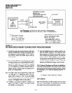
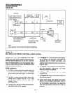
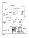
3.23 Door Lock Control (PIOU or PIOUS). Con-
figure the PIOU or PIOUS for the door lock control
INSTALLATION-PERIPHERALS
SECTION 100-816-207
MARCH 1993
function in accordance with the following steps (refer
to Figure 7-6 and 7-7):
NOTE:
Only one door lock control is available using an
optionalintertace PCB (PIOU or PIOUS), bemuse
only one interface PCB is allowed.
1)
2)
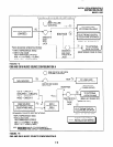
3A)
3B)
4)
Access Program 77-l. Set LED 07 for the door
lock control function.
Access Program 77-l. Set LED 20 to OFF for a 3-
second door lock activation time, or set LED 20 to
ON for a 6-second door lock activation time.
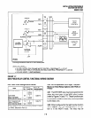
Set the PI0 jumper plug on the PIOU to the
MAKE or BREAK position, as required:
l
MAKE-Shorts the normally open con-
tacts (pins 7 and 32) when a station’s
door lock button is pressed.
l
BREAK-Opens the normally closed
contacts (pins 7 and 32) when a station’s
door lock button is pressed.
Solder the WI jumper plug on the PIOUS to the
MAKE or BREAK position as required:
l
MAKE-Shorts the normally open con-
tacts (DET and DER) when a station’s
door lock button is pressed.
l
BREAK-Opens the normally closed
contacts (DETand DER) when astation’s
door lock button is pressed.
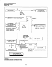
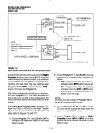
Refer to Figure 7-8 for wiring/interconnecting
details. Connect the PIOU or PIOUS to the
MDF as required for the door lock control
function.
3.24 DK8 and DK16 DDCB Door Lock Control.
In addition to the door lock control provided by the
PIOU or PIOUS (DK16 only), each door phone/lock
control box (DDCB) installed provides one door
lock control. Only two DDCBs can be installed in a
system: On DK8 a DDCB can be connected to
Circuit 3 (Port 02) and/or Circuit 4 (Port 03); on
DK16 a DDCB can be connected to the circuit 5
(Logical Port 04) of the Base Unit Digital telephone
circuit set and to circuit 1 of the KCDU or PDKU
7-7