


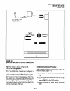

3 POWER SUPPLY REMOVAL AND
REPLACEMENT
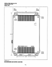
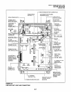
3.00 The power supply comes factory-installed in
the Key Service Unit (Figure 4-5); if necessary, it
can be removed and replaced.
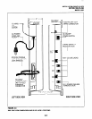
3.10 Power Supply Removal (Figure 4-5)
1)
2)
3)
4)
5)
6)
7)
Make sure that the power supply switch is OFF
and that the AC power cable is not plugged
into an outlet. Confirm that green AC LED is
not lit.
Loosen the screws on the front cover of the
Key Service Unit, and remove the cover.
Unplug HPFB cable from BATT connector of
powersupplyanddisconnecttheHPFBground
wire (Figure 4-5).
Unplug the AC cable from the CNI connector
on the power supply (Figure 4-5).
Remove the FG screw, and disconnect the
green third wire ground ring terminal (Figure
4-5).
Unplug the DC cable from the CN3 connector
on the power supply (Figure 4-5).
Remove the top two, and bottom left corner
screws that attach the power supply to the Key
Service Unit. Remove power supply.
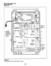
3.20 Power Supply Replacement (Figure 4-5)
1) Set the power supply in its proper place in the
Key Service Unit (Figure 4-5).
2) Secure the power supply to the Key Service
Unit with the top two, and bottom left corner
screws.
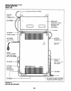
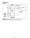
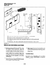
4.10 DK8 Power Failure Emergency Transfer
Installation.
Install the dedicated emergency
standard telephone as follows (see Figure 4-6):
1) Connect a standard telephone to the PFl
connector in the Base Unit.
4.20 DK8 Power Failure Emergency Transfer
Test.
3) Install the green third wire ground ring terminal
with the FG screw.
1) Turn the system power switch off.
4) Plug the AC cable into the CNl connector on
2) Lift the emergency standard telephone hand-
the power supply (Figure 4-5).
set, and verify that there is CO dial tone.
5)
6)
7)
Plug the DC cable into the CN3 connector on
the power supply (Figure 4-5).
Plug the AC power cable into an outlet and
turn ON the power supply switch.
Test QPSU8 power supply according to the
DK8 Hardware Fault Isolation procedure,
Section 100-816-500, Paragraph 6.
8)
Plug HPFB cable into BATT connector of
power supply and reconnect the HPFB ground
wire (Figure 4-5).
9)
Reinstall the cover on the key service unit.
INSTALLATION-OK8 KSU & PCB
SECTION 100-816-204
MARCH 1993
4 DK8 POWER FAILURE EMERGENCY
TRANSFER OPTION
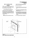
4.00 A dedicated standard telephone can be con-
nected to the Power Failure Transfer Interface
(PFl) on the Key Service Unit to provide power
failure backup. During normal operation, this
telephone cannot be used-it does not count as a
station; so it does not reduce the system’s 10
maximum station capacity. But if there is a power
failure, the telephone will automatically be con-
nected to CO line 1. When power is restored, the
system will automatically resume with its normal
station and CO line assignments, and the dedi-
cated telephone will become inoperative again.
4-5