


INSTALLATION-STATION APPARATUS
SECTION 100-816-206
MARCH 1993
Bell-even if a headset is also installed on the
HHEU.
6)
7A)
7B)
w
=3)
W
W
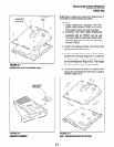
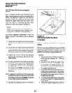
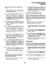
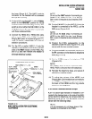
Position the HHEU PCB on the standoffs
inside the base (Figure6-lo), and secure with
the two provided screws.
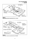
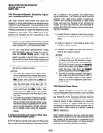
For 2000-series digital telephones, refer to
Figure 6-7 (DKT2010-H) or Figure 6-8
(DKT201 O-SD, DKT2020-S, DKT2020-SD),
and connect the wire plug of the HHEU PCB
to the HHEU connector on the printed circuit
board (PCB) on the telephone.
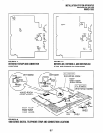
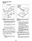
For 1000~series digital telephones, refer to
Figure 6-9, and connect the wire plug of the
HHEU to the HHEU connector on the PCB of
the telephone.
For 2000-series digital telephones, refer to
Figure 6-7 (DKT2010-H) or Figure 6-8
(DKT201 O-SD, DKT2020-S, DKT2020-SD),
and locate the EX.SP strap on the PCB in the
telephone. Cut the strap if an HESB will be
connected to the HHEU.
For 1000~series digital telephones, refer to
Figure 6-9, and locate the EX.SP strap on the
upper PCB in the telephone, and cut it if an
HHEU will be connected to an HESB for the
Loud Ringing Bell option.
For 2000series digital telephones, refer to
Figure 6-7 (DKT2010-H) or Figure 6-8
(DKT201 O-SD, DKT2020-S, DKT2020SD),
and locate the HHEU strap on the PCB in the
telephone. Cut the strap if a headset will be
connected to the HHEU.
For lOOO-series digital telephones, refer to
Figure 6-9, and locate the HHEU strap on the
upper PCB in the telephone. Cut the strap if
an HHEU will be connected to a headset.
NOTE:
If the HHElJ PCB is removed from the tele-
phone, the HHEU strap must be replaced for
proper telephone operation.
IO) Reinstall the telephone base, and secure it
with its four captive screws.
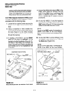
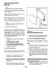
11) To adjust the volume of the HESB Loud
Ringing Bell: Call the telephone connected to
the HESB, and adjust the volume control on
the back of the HESB and the ring volume
control on the telephone.
3.40 Carbon Headset/Handset Straps
3.41 If a carbon-type handset or headset is con-
nected to the handset jack on the side of the
telephone, two jumper straps inside the telephone
must be cut. Cut the straps in accordance with the
following steps:
NOTE:
It is not necessary to cut these straps if the
headset is connected to the HHEU.
1)
24
2B)
3)
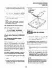
Loosen the four captive screws securing the
telephone base (Figure 6-l), and remove the
base.
For 2000~series digital telephones refer to
Figure 6-7 or 6-8, and cut the CARBON straps,
W201 and W202.
For 1000~series digital telephones, refer to
Figure 6-9, and cut the CARBON straps,
(W301 and W302 on the DKTI 020-SD; W201
and W203 on the DKT1020-H).
Reinstall the telephone base, and secure it
with its four captive screws.
3.50 Beep Strap
3.51 A “beep” sounds whenever a dialpad button
or feature button is pressed on a digital telephone.
To eliminate this beep follow the procedure below:
1)
w
2W
3)
Loosen the four captive screws securing the
telephone base (Figure 6-l), and remove the
base.
For 2000-series digital telephones, refer to
Figures 6-7 or 6-8, and cut the BEEP strap.
For IOOO-series digital telephones, refer to
Figure 6-9, and cut the BEEP strap.
Reinstall the telephone base, and secure it
with its four captive screws.
6-9