INSTALLATION-WIRING DIAGRAMS
SECTION lOO-816-208
MARCH1993
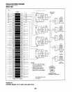
TO BASE UNIT (P5)
W/FEMALE CONNECTOR BR’DG’NG
STATION CABLING
Tl (VOICE/DATA)4
CIRCUIT 3 TO DKT34
1
CIRCUIT 4 TO DKT44
OR PDIU-DS OR
DDCB
1
CIRCUIT 5 TO DKT55
OR PDIU-DS
8
z
R-Em
I 34
s
5
:
s
%
CIRCUIT 6 TO DKT65
OR PDIU-DS
2
Y
1
CIRCUIT 7 TO DKT75
OR PDIU-DS
Y
CIRCUIT 8 TO DKTB5
RELAY
CONTACTS
NOT USED
STD TEL3
CIRCUIT I
--
JACKETED TWISTED PAIRS
24AWG (1 OR 2 PAIR, SEE NOTE 2)
‘-tt--j-1
“I PRl
I
654321
r A-----Y\\
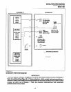
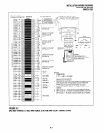
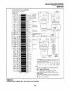
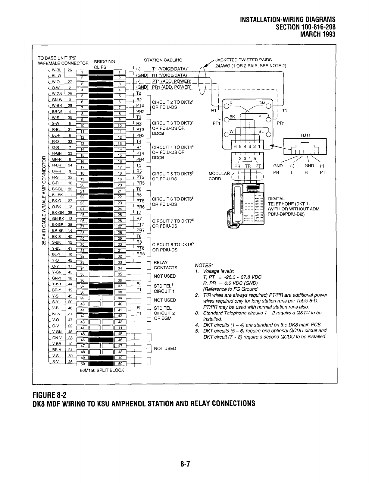
FIGURE 8-2
DK8 MDF WIRING TO KSU AMPHENOL STATION AND RELAY CONNECTIONS
V-GN 1 48
66M150 SPLIT BLOCK
MODUL
CORD
DIGITAL
TELEPHONE (DKT 1)
(WITH OR WITHOUT ADM,
PDIU-DIIPDIU-D12)
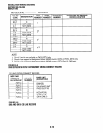
NO JES:
1. Voltage levels:
T, PT = -26.3 - 27.8 VDC
R, PR = 0.0 VDC (GND)
(Reference to FG Ground
2.
T/R wires are always required; PT/PR are additional power
wires required only for long station runs per Table 8-D.
PT/PR may be used with normal station runs also.
3. Standard Telephone circuits 1 - 2 require a QSTU to be
installed.
4. DKT circuits (1 - 4) are standard on the DK8 main PCB.
5. DK7 circuits (5 - 6) require one optional QCDU circuit and
DKT circuit (7 - 8) require a second QCDU to be installed.
8-7


