INSTALLATION-PERIPHERALS
SECTION 100-816-207
MARCH 1993
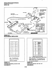
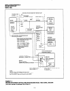
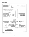
KSTU OR PSTU
CIRCUIT 4
OR
QSTU,
CiRCUlT 2
(PORT 19)
’ UNIVERSITY SOUND
MODEL TM-2
TELEPHONE ADAPTOR
RCA JACK
(OR EQUIVALENT)
*
1
BGM MUSIC
HIGH LEVEL
OUTPUT
(
SOURCE
6OOfi OUTPUT
OR 8Q OUTPUT
4
PHONE LINE
SEE
PROGRAM 19
FOR SLOT KSTU OR PSTU ASSIGNMENT
SEE
PROGRAM 10-2,
LED 10 FOR QSTU, PORT 19 ASSIGNMENT
NOTE:
1. UNIVERSITY SOUND
1327 Ralston Avenue
Syimar, Ca. 91342-7607
Phone: (818) 362-9516
*BGM SOURCE SPECIFICATIONS:
l
INPUT IMPEDANCE: 600R
l
INPUT VOLTAGE:
RECOMMENDED LEVELS,
MIN. = 0.14 VRMS (-15 dBm)
MAX. = 0.77 VRMS (0 dBm)
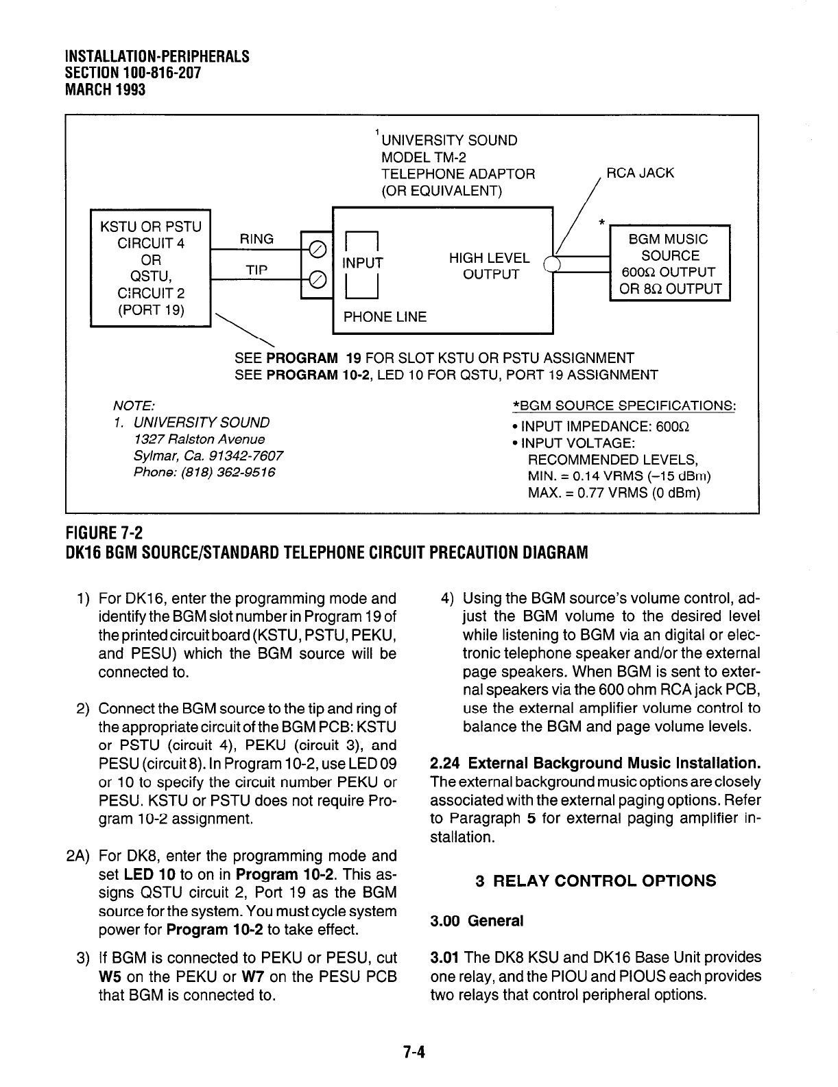
FIGURE 7-2
DK16 BGM SOURCE/STANDARD TELEPHONE CIRCUIT PRECAUTION DIAGRAM
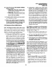
1) For DK16, enter the programming mode and
identify the BGM slot number in Program 19 of
the printedcircuit board (KSTU, PSTU, PEKU,
and PESU) which the BGM source will be
connected to.
2) Connect the BGM source to the tip and ring of
the appropriate circuit of the BGM PCB: KSTU
or PSTU (circuit 4), PEKU (circuit 3), and
PESU (circuit 8). In Program 1 O-2, use LED 09
or 10 to specify the circuit number PEKU or
PESU. KSTU or PSTU does not require Pro-
gram 1 O-2 assignment.
4) Using the BGM source’s volume control, ad-
just the BGM volume to the desired level
while listening to BGM via an digital or elec-
tronic telephone speaker and/or the external
page speakers. When BGM is sent to exter-
nal speakers via the 600 ohm RCA jack PCB,
use the external amplifier volume control to
balance the BGM and page volume levels.
2.24 External Background Music Installation.
The external background music options are closely
associated with the external paging options. Refer
to Paragraph 5 for external paging amplifier in-
stallation.
2A) For DK8, enter the programming mode and
set
LED 10
to on in
Program 10-2.
This as-
signs QSTU circuit 2, Port 19 as the BGM
source for the system. You must cycle system
power for
Program 10-2
to take effect.
3 RELAY CONTROL OPTIONS
3.00 General
3) If BGM is connected to PEKU or PESU, cut
3.01
The DK8 KSU and DK16 Base Unit provides
W5
on the PEKU or W7 on the PESU PCB one relay, and the PIOU and PIOUS each provides
that BGM is connected to.
two relays that control peripheral options.
7-4


