


-.
NOTE:
The PDIU-DI always operates as a DCE de-
vice; therefore, unlike the PDIU-DS, it has no
in ternal jumpers.
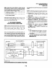
3) Connect the appropriate RS-232 cable be-
tween the PDIU-Dl’s DB-25 female connector
and the PC’s appropriate asynchronous serial
communications port connector (COM port).
IMPORTANT NOTE!
Check the PC manufacturer’s serial com-
munication port interface documentation
for correct RS-232 pin requirements; re-
quirements vary with each manufacturer.
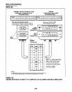
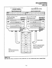
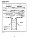
The number of EIA RS-232 signals required
(8,9, or IO wires) depends on the applica-
tion. When EIA signal requirements are not
known, connect the 10 EIA signals listed in
Paragraph 10.20. Figures 7-25 and 7-30
provide diagrams for connecting RS-232
cables between PDIU-Dls and Toshiba lap
top, and IBM, XT and AT PCs.
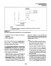
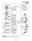
4) Set the PDIU-DI DIP switch (SW1 -1 - 4) for the
desired application. Figure 7-32 shows the
DIP switch locations and Paragraph 10.30
describes switch functions.
5) Access Program 20 to configure the PDIU-DI
for DTE-type connection and Program 39 for
data button assignments of the digital tele-
phone connected to the PDIU-DI.
Program 20
l
The port number entered for the PDIU-DI
in Program 20 is the port number of the
digital telephone to which the PDIU-DI is
connected.
l
LED 01: Should always be ON for PDIU-
DI ports.
l
LEDO2: Should be ON for PDIU-DI ports,
unless the PC user will never use DIU AT
commands (other than ATDD, ATDT,
and ATD) and never require the PDIU-DI
to send result codes to display on the PC
display screen. Frequently, it is difficult
to determine the full extent of these
INSTALLATION-PERIPHERALS
SECTION 100-816-207
MARCH 1993
requirements; so it is recommended to
turn LED 02 ON. See the Data interface
UserGuidefor information regarding DIU
AT commands and result codes.
LEDs 03 and 04: Should be OFF for
PDIU-DI ports.
LED 05: Should be ON if the system is
installed behind a PBX or Centrex that
uses access codes to make external
calls or to insert a pause following DIU
access of an outside line.
LEDs 17 w 20: Used to establish data
security groups. PDIU stations are only
allowed to make calls to PDlUs in the
same data group to which they are as-
signed.
Program 39
l
The following data call buttons can be
assigned digital telephones equipped with
PDIU-Dls: Data Call, and Modem.
Assign SD buttons to data devices as
required. Do not assign DSS buttons to
data devices; DSS buttons are used for
voice calls only.
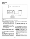
10.50 PDIU-DS to Printer Installation
10.51 STRATA DK8 and DK16 enables serial print-
ers (laser, dot matrix, orothertypes) to be connected
to stand-alone data interface units (PDIU-DSs).
Digital telephones equipped with PDIU-Dls can
share access to these printers. Serial printers op-
erate as DCE or DTE devices, depending on the
vendor; the PDIU-DS can be connected to either
type, since it can be configured as a DTE or DCE
device. (The PDIU-DS comes from the factory
configured as a DCE device.) Follow the steps
below to install the PDIU-DS to a serial printer.
NOTES:
1. Only serial printers (not parallel) that con-
form to EIA RS-232 signaling require-
ments can be connected to PDIU-DSs.
2. In rare applications, it may be desired to
connectprinters to PDIU-D/s. Refer to the
printer’s installation instructions.
7-37