


INSTALLATION-PERIPHERALS
SECTION 100-816-207
MARCH 1993
IMPORTANT NOTE!
Modems must be “smart modems” that
respond to AT commands and return re-
sult codes. Modems are customer-sup-
plied.
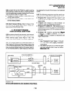
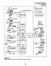
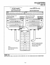
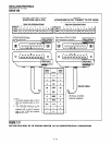
10.62 A modem(s) can be accessed internally for
outgoing data calls or externally for incoming data
calls. Modems operate as DCE devices; so PDIU-
DSs that are connected to them must be configured
to operate like a DTE device. In the example
installation in Figure 7-24, the line side of the two
modems are connected to KSTWPSTWPESU ports
to establish a modem pool; however, the line side
of modems could be connected directly to a dedi-
cated CO line. If modems are connected directly to
telephone network CO lines, automatic transfer of
CO line voice calls to system modems (data call)
will not function as described in the Data interface
User Guide. For best operation and utilization of
CO lines and modems, it is recommended to con-
nect modems to QSTU, PSTU or KSTU standard
station ports in a modem pool configuration. The
RS-232 side of the modem connects to the PDIU-
DS with standard RS-232 cables; the PDIU-DS line
side (RJ-11 connector) always connects to its own
individual digital port. Use the following instructions
to install modems to PDIU-DSs.
1) Configure the PDIU-DS as a DTE device:
Disassemble the PDIU-DS and place jumper
plugs Pl - P9 in the “B-C” position (MODEM).
Reassemble the PDIU-DS and mark “B-C” on
the bottom identification label for future refer-
ence. (Paragraph 10.70 provides PDIU-DS
disassembly/assembly instructions and Fig-
ure 7-31 provides jumper plug information.)
2) Connect the PDIU-DS to the appropriate Digi-
tal port circuit per the wiring diagrams in Sec-
tion 100-816-208.
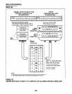
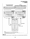
3) Connect the appropriate RS-232 cable be-
tween the modem and the PDIU-DS. Figure 7-
28 shows an example PDIU-DS to “smart
modem” RS-232 connection.
IMPORTANT NOTE!
All ten PDIU-DS EIA leads (signals) should
be connected to the modem. Consult the
modem’s documentation for correct RS-
232 pin requirements; the requirements
may vary with each manufacturer.
4) Connect the line side of the modem to a
QSTU, PSTU, KSTU or PESU standard tele-
phone circuit or a dedicated CO line (consult
the modem’s documentation to install the it to
a CO line). Section 100-816-208 provides
QSTU, KSTWPESWPSTU station port wiring
information.
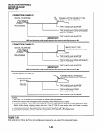
5) Set the PDIU-DS DIP switch (SWl-1 - 4) for
the desired application. Figure 7-32 shows the
DIP switch location and Paragraph 10.30
describes switch functions.
NOTE:
If the modem tracks carrier detect (DCD,
AT&C7), SW1(4)shouldbe”ON,“andSWl(2)
should be OFF when PDIU-DS is connected
to a modem.
6) Use the programs below to configure the
PDIU-DS to connect to an asynchronous
modem (see Programming Section 100-816-
302 for explanations and record sheets).
Program 20
l
LED 01: Should always be ON for PDIU-
DS ports
l
LED 02: Should be ON for PDIU-DS ports
connected to modems, enabling the use
of AT commands and result codes when
incoming calls are made from outside the
system to modems connected to PDIU-
DSs.
l
LED 03: Should be set ON for PDIU-DS
ports connected to modems.
l
LED 04: Should always be ON for PDIU-
DS ports.
l
LED 05: Should be ON if the system is
installed behind a PBX/Centrex that uses
access codes to place outgoing trunkcalls.
7-39