


Installing the MDW 9030P Pocketphone
2-21
Installing a Single Carrier on a WallInstalling a Single Carrier on a Wall
Installing a Single Carrier on a WallInstalling a Single Carrier on a Wall
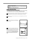
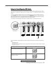
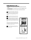
Installing a Single Carrier on a Wall
■
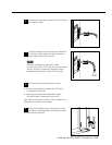
Install high on wall, leaving 6–12 inches (15.2–30.5 cm) between antennas and
ceiling
■
Never install or remove a radio module from a carrier that is plugged into a wall
outlet (hot insertion)
■
See “Key Components” earlier in this chapter for additional picture detail
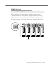
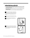
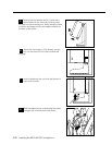
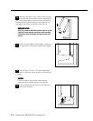
Perform the tests described in "Wireless Test
Mode" earlier in this chapter to determine the
optimal placement of the radio module. To perform
the tests, all you need is an electrical outlet for the
radio module and a charged battery pack in the
handset.
1
2
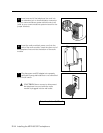
Check to make sure the carrier’s power cord is
unplugged from the wall outlet before continuing.
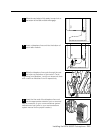
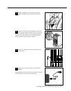
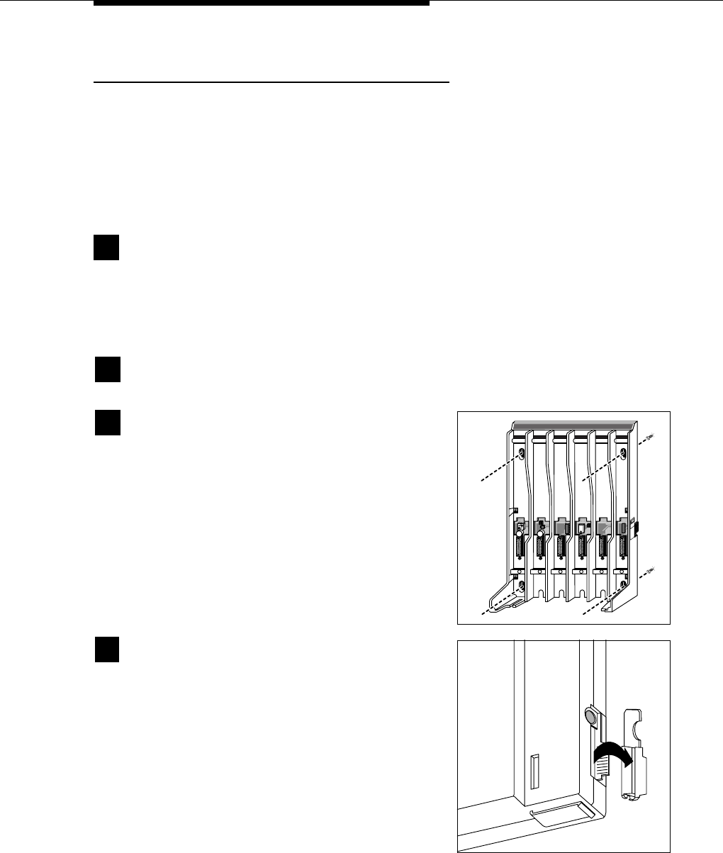
Remove the plastic cap covering each radio
module’s card edge before inserting the radio
modules into the carrier.
4
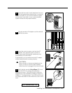
Place the carrier against the wall. Choose a loca-
tion backed by a wooden stud (if unavailable, use
toggle bolts instead of the supplied wood screws). Hold
the carrier straight; use a level if needed. Using a nail or
pencil, mark screw locations through the four wall-mount
holes.
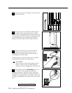
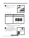
Start the screws, leaving the screw heads protruding
approximately
1
/
2
" (12 mm) from the wall. Place the car-
rier assembly over the screws, then slide it downward to
lock it into place. Tighten the screws.
3
1 2 3 4
6
4
T
RANS
T
ALK
21
O N
21
O N
5
CAUTION
USE ONLY
AT&T CABLE
P⁄N 847667896
IN
OUT
OUT OF SYNC