


11 - 7
Communication
Dolphin terminals support USB communications out of the box. The base also supports USB communi-
cations via the USB port located on the back. The base acts as a USB device by interfacing the USB
signals of the Dolphin terminal to the USB of the host workstation. Using a standard USB cable, the
base’s USB interface allows the Dolphin terminal to communicate with a workstation.
Requirements
• A base powered by a power cable and power adapter cable
• A standard USB (Type A to B) communication cable
• A work station running Windows 98 Second Edition, Windows Me, Windows 2000, Windows NT (4.0
SP6 or higher), Windows XP, Windows Vista, or Windows 7.
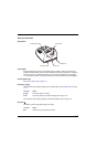
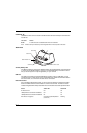
Setting Up and Connecting the Dolphin Terminal to the HomeBase
1. Connect power to the HomeBase (see Power on page 11-5).
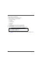
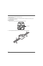
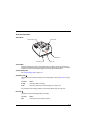
2. Plug the USB communication cable into the USB port on the back of the base.
Note: The Dolphin terminal should always be removed from the HomeBase when connecting or disconnecting
the USB cable.
3. Connect the other end of the USB cable to the host workstation.
4. Insert the Dolphin terminal into the terminal well of the base. The Dock LED illuminates blue.
5. Touch Turn on USB storage when the USB Mass Storage screen opens.
6. The computer views the terminal as an external USB storage drive. You can copy, delete and/or
move files or folders between the computer and the installed microSD card as you would with any
other storage drive (e.g., cut and paste or drag and drop).
7. When you are finished transferring files, touch Turn off USB storage.
Note: This base cannot be daisy-chained.
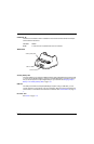
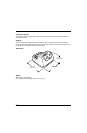
Mounting the HomeBase
Set the base on a dry, stable surface, such as a desktop or workbench near an electrical outlet. The user
should be able to view and operate the Dolphin terminal while it is in the base. When choosing a
mounting location, bear in mind that the location must allow users' easy access to the Auxiliary Battery
Well and the back panel of the HomeBase where the USB port and the power jack are located.
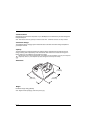
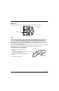
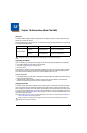
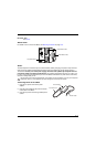
Optional DIN Rail Mount
A DIN rail (7.5 X 35 mm) may be installed on the bottom of the base to provide the optional security of
mounting the base to a flat horizontal surface with hardware.
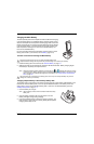
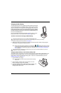
Additional Hardware
• DIN Rail, Qty. 1
• 3/16 in. dia x 5/8 in. long pan head screw, Qty. 2