


NDA-24305 CHAPTER 6
Page 283
Revision 1.0
IS-11572 (LAYER 3 SPECIFICATIONS FOR INTER-PBX SIGNALING PROTOCOL)
4. Programming
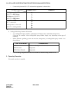
STEP 1: ASYD - Assign the following data.
SYS-1 Index 186 bit6=1 (ISDN/CCIS is in service)
187=00 Hex
220 bit6=0 (ISDN is in service)
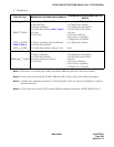
STEP 2: Assign the numbering plan data for call origination.
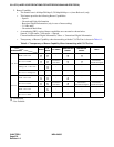
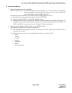
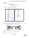
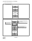
STEP 3: ARTD - Assign the route data for Bch and Dch at each physical interface.
Note 1:
Depending on the level diagram of the network. Data “4” is for standard.
Note 2:
Note that each office must be assigned a different value to avoid collision at the time of call origination.
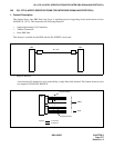
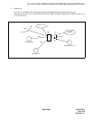
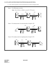
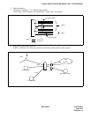
TRKS=0 (When PRT/DCH is set as “User side” by DIP switch.)
TRKS=1 (When PRT/DCH is set as “Net side” by DIP switch.)
Note 3:
Assign “1” when the number display on LCD of terminal is required.
Note 4:
Assign “1” when the User-to-User signaling notification is required.
Note 5:
Assign “1” when the multi-rate bearer service is used.
B-channel route data
CDN 2 (ONSG) = 2
4(INSG) = 2
5(TF) = 3
6(TCL) = 4
7(L/T) = 1
8(RLP) = 2
15 (LSG) = 12
28 (ANS) = 1
30 (PAD) = 4
Note 1
31 (OGRL) = 1
32 (ICRL) = 1
34 (GUARD) = 1
45 (A/D) = 1
49 (TRKS) = 0/1
Note 2
50 (DPLY) = 1
Note 3
65 (INT) = 10
66 (DC) = 15
113 (UUI) = 1
Note 4
118 (BOB) = 1
Note 5
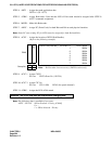
D-channel route data
CDN 2 (ONSG) = 2
4(INSG) = 2
5(TF) = 3
6(TCL) = 4
7(L/T) = 1
15 (LSG) = 13
30 (PAD) = 7
31 (OGRL) = 1
32 (ICRL) = 1
34 (GUARD) = 1
45 (A/D) = 1
65 (INT) = 10
118 (BOB) = 1
Note 5
PRT
PRT
IS-11572
PRT
Dip SW : User side
ARTD : TRKS = 0
Dip SW : Net side
ARTD : TRKS = 1