


116 Chapter 4
C:\Spk\Ref\RefGuideRevE\Tools.fm
Overview of the Test Set’s Built-In Tools
Using the Spectrum Analyzer
Defining the Fixed Mask’s Limits
1. Set the Edit Mask field to the limit you want to edit (Upper or
Lower).
You might want to set the Mask Beep field to Off while you are
defining the mask.
2. Set the Mask Type field to Fix.
3. Set the #Pts field to the number of points you want defined by the
mask. You can define up to 15 points. The starting point is always
the left graticule on the display, and the end point is always the right
graticule on the display.
To define a straight-line mask, set the number of points to 1. The
default mask is a straight line at the top of the display.
4. Set the EditPt field to the point you want to define.
5. Set the Lvl and Freq fields to the frequency and level you want for
the point you chose in the EditPoint field.
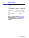
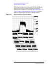
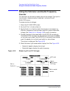
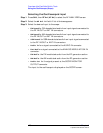
In Figure 4-27 the frequency and level settings for each point are as
follows:
Figure 4-27 Setting the Spectrum Analyzer Mask
Table 4-2 Settings for mask in Figure 4-27
Point Level Frequency
1 −50 dBm 1799.7000
2 1 dBm 1799.7000
3 1 dBm 1800.3000
4 −50 dBm 1800.3000 MHz
Point 1
Point 2
Point 4
Point 3
Set number of point here.
Select which point to set
or edit.
Set the level of the
Set the frequency of the
point.
Turn the beeper off or on.
Read the pass/fail
samask.pcx