


94 Chapter 4
C:\Spk\Ref\RefGuideRevE\Tools.fm
Overview of the Test Set’s Built-In Tools
Using the RF Tools Program
CAUTION
Damage may result if the power input to the Test Set’s ANT IN port
exceeds 60 mW (which is equivalent to 18 dBm). Damage may also
result to the unit-under-test if it is overdriven by the DUPLEX OUT
power level. To avoid damage to the ANT IN port, enter an
over-estimate gain value for the Max expected gain in dB parameter.
To avoid damage to the unit under test, ensure a low power level for the
DUPLEX OUT level in dBm parameter.
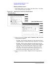
6. Press
k1
(Begin Tst) or position the cursor at Begin and select it.
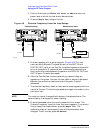
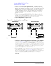
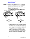
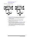
Figure 4-13 Swept Return Loss Setups
7. A setup screen appears with a diagram of the necessary connections,
similar to Figure 4-13. This is the calibration phase of the test to
obtain a reference level for the device being tested. A VSWR bridge
or a directional coupler and two 6 dB pads are connected to the Test
Set. The pads are used to reduce impedance mismatch errors
between the VSWR bridge and the DUPLEX OUT and ANT IN ports
on the Test Set. A reference level is measured first with a short on
the DUT (Device Under Test) port of the VSWR bridge. An open can
be used as well, but the open must not be blocked in any way that
might cause the signal to be reflected back. For example, using the
open setup inside a van or other enclosed area may introduce
inaccuracies in the measurement. Setup the hardware, then press
k1
(Proceed) or the knob to continue.
8. Another setup screen appears. Attach the device being tested. Press
k1
(Proceed) or the knob to continue.
VSWR Bridge
PARALLEL PORT 15
AUDIO OUT
ANALOG
MODULATION
IN
AUDIO IN
SCOPE
MONITOR
OUT
EXT SCOPE
TRIG IN
VIDEO
OUT
ANT IN DUPLEX OUT
CHIP CLOCK
1.2288
MHz OUT
FRAME
CLOCK
OUT
EVEN
SECOND
SYNC IN
TRIGGER
QUALIFIER
IN
10 MHz
REF OUT
EXT
REF IN
RF IN/OUT
IN
BASEBAND OUT
HI
LO
QI
PARALLEL PORT 16
SERIAL 9
SERIAL 10
SERIAL 11
16X
CHIP CLOCK
19.6608
MHz OUT
DATA
8935
DUPLEX OUT
ANT IN
6dB Pad 6dB Pad
Calibration Setup
REFL.
OUT
IN
TEST PORT
VSWR Bridge
PARALLEL PORT 15
AUDIO OUT
ANALOG
MODULATION
IN
AUDIO IN
SCOPE
MONITOR
OUT
EXT SCOPE
TRIG IN
VIDEO
OUT
ANT IN DUPLEX OUT
CHIP CLOCK
1.2288
MHz OUT
FRAME
CLOCK
OUT
EVEN
SECOND
SYNC IN
TRIGGER
QUALIFIER
IN
10 MHz
REF OUT
EXT
REF IN
RF IN/OUT
IN
BASEBAND OUT
HI
LO
QI
PARALLEL PORT 16
SERIAL 9
SERIAL 10
SERIAL 11
16X
CHIP CLOCK
19.6608
MHz OUT
DATA
8935
DUPLEX OUT
ANT IN
6dB Pad 6dB Pad
Measurement Setup
REFL.
OUT
IN
TEST PORT
Attach device to
be tested.
sretloss.eps
Short