


278 Chapter 8
C:\Spk\Ref\RefGuideRevE\Enc-dec.fm
Signaling Encoder and Decoder - Screens and Control Fields
Control Fields for the Signaling Encoder and Decoder
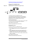
Trigger Pattern (bin)
This field allows you to enter a specific bit pattern to filter displayed
information. The decoder only displays the received data when this
binary pattern is encountered immediately after triggering. This is
helpful when you only want to display messages containing very
specific information.
The trigger pattern is entered as a sequence of ones, zeros, and dots. A
dot will cause the decoder to trigger for either a one or a zero in that bit
position in the received data stream.
Operating Considerations
This function is not available for decoding NAMPS-NTACS RVC
information.
Screens Where Field is Present
SIGNALING DECODER (Modes: AMPS-TACS, NAMP-NTAC)
Trig Level
The trigger level indicates the minimum signal level required to begin a
measurement that has been “armed.” The level is adjusted by changing
the Input Level field’s setting.
The input level should be set high enough to prevent false triggering,
but low enough to allow triggering for valid signals. This may require
you to set the input level well below the expected level.
Screens Where Field is Present
SIGNALING DECODER (Modes: AMPS-TACS, NAMP-NTAC, Func
Gen)