


100 Chapter 4
C:\Spk\Ref\RefGuideRevE\Tools.fm
Overview of the Test Set’s Built-In Tools
Using the RF Tools Program
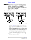
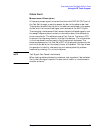
Figure 4-17 Cable Fault Setups
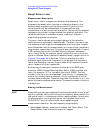
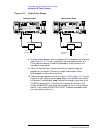
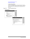
8. A setup screen appears with a diagram of the necessary connections
(see Figure 4-17). It is very important that the power divider is a
2-way resistive device. Press
k1
(Proceed) or the knob after the
hardware is connected.
9. After the Test Set has finished calibrating, a second diagram
appears on the screen. Connect the cable to be tested. Press
k1
(Proceed) or the knob to continue.
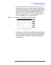
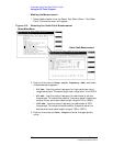
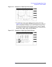
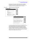
10.The plot screen appears similar to Figure 4-18 on page 101. To save
the plot to a PC card, press k4 (Save Plot) and use the knob to enter
a filename. Press
k5
(Scr Dump) to send the image to a printer or to
the BTS Laptop Utility. Directions will appear at the top of the
screen. Press PRINT and allow the image to print to the connected
device. Then, press PAUSE/CONTINUE. Press
k1
(Proceed) when
you are ready to continue.
Resistive Splitter
50 Ohm
Termination
PARALLEL PORT 15
AUDIO OUT
ANALOG
MODULATION
IN
AUDIO IN
SCOPE
MONITOR
OUT
EXT SCOPE
TRIG IN
VIDEO
OUT
ANT IN DUPLEX OUT
CHIP CLOCK
1.2288
MHz OUT
FRAME
CLOCK
OUT
EVEN
SECOND
SYNC IN
TRIGGER
QUALIFIER
IN
10 MHz
REF OUT
EXT
REF IN
RF IN/OUT
IN
BASEBAND OUT
HI
LO
QI
PARALLEL PORT 16
SERIAL 9
SERIAL 10
SERIAL 11
16X
CHIP CLOCK
19.6608
MHz OUT
DATA
8935
DUPLEX OUT
ANT IN
Calibration Setup
OUT OUT
IN
Resistive Splitter
OUT OUT
IN
PARALLEL PORT 15
AUDIO OUT
ANALOG
MODULATION
IN
AUDIO IN
SCOPE
MONITOR
OUT
EXT SCOPE
TRIG IN
VIDEO
OUT
ANT IN DUPLEX OUT
CHIP CLOCK
1.2288
MHz OUT
FRAME
CLOCK
OUT
EVEN
SECOND
SYNC IN
TRIGGER
QUALIFIER
IN
10 MHz
REF OUT
EXT
REF IN
RF IN/OUT
IN
BASEBAND OUT
HI
LO
QI
PARALLEL PORT 16
SERIAL 9
SERIAL 10
SERIAL 11
16X
CHIP CLOCK
19.6608
MHz OUT
DATA
8935
DUPLEX OUT
ANT IN
Measurement Setup
Attach device to
be tested.
cablef.eps