


266 Chapter 8
C:\Spk\Ref\RefGuideRevE\Enc-dec.fm
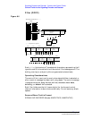
Signaling Encoder and Decoder - Screens and Control Fields
Control Fields for the Signaling Encoder and Decoder
Input Level
This field specifies the expected data signal level (after de- emphasis if
used). The higher the level of signal expected by the analyzer, the
higher the trigger level is set. See “De-emphasis Effects on Input Level”
on page 266.
Operating Considerations
The unit-of-measure is determined by the AF Anl In setting.
The input level should be set high enough to prevent false triggering,
but low enough to allow triggering for valid signals (typically about 3
kHz). This you to set the input level well below the expected level.
When using de-emphasis, the Input Level setting may need to be
reduced significantly to properly decode the incoming signal.
De-Emphasis is enabled/disabled using the De-Emphasis field on the
AF ANALYZER screen.
If de-emphasis is used (by setting the AF Analyzer’s De-Emphasis field
to 750 µs), the Input Level should be set to about 1/5 of the measured
signal’s level. For example, a 1 kHz, 1 Vpeak sinewave into the AF
Analyzer’s input requires an Input Level of approximately 0.212 V to
trigger correctly.
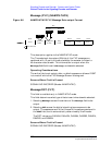
De-emphasis Effects on Input Level
De-emphasis is a single-pole, low-pass filter with a 212.2 Hz corner
frequency. It is enabled/disabled using the De-Emphasis field on the AF
ANALYZER screen. The input level is the expected level at the output
of the de-emphasis network.
Assuming a mean DTMF frequency of approximately 1 kHz, decoding
with de-emphasis on (set to
750 µs) requires the input level to be set to 212/1000 = 0.212 times the
peak deviation, or about 1/5 the incoming level of the tone.