


262 Chapter 8
C:\Spk\Ref\RefGuideRevE\Enc-dec.fm
Signaling Encoder and Decoder - Screens and Control Fields
Control Fields for the Signaling Encoder and Decoder
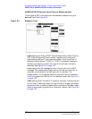
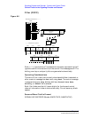
Data Level
This setting determines the signal level change that occurs when a
logical high (1) or low (0) is output. The unit-of-measure used depends
on the AFGen2 To setting. The direction of the output level change
depends on the Polarity setting.
Screens Where Field is Present
SIGNALING ENCODER (Modes: AMPS-TACS, NAMP-NTAC)
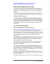
Data Rate (analog)
Signaling Decoder
This measurement field displays the data rate in bits-per-second for the
data stream being received.
The encoder screen’s Data Rate field tells the decoder how fast the
incoming message is being sent. Set the Data Rate field’s value before
using the AMPS-TACS or NAMPS-NTACS decoder.
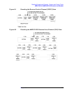
Signaling Encoder
This field specifies how fast the data stream is output in
bits-per-second.
This setting is also used to determine the turn off code frequency (TOC
frequency Hz = Data Rate in bps). Example: 1000 bps = 1 kHz
This field specifies the data rate for the signal being decoded, and must
be set before using the AMPS-TACS/NAMPS-NTACS decoder.
Screens Where Field is Present
SIGNALING DECODER (Modes: AMPS-TACS, NAMP-NTAC)
SIGNALING ENCODER (Modes: AMPS-TACS, NAMP-NTAC)