


92 Chapter 4
C:\Spk\Ref\RefGuideRevE\Tools.fm
Overview of the Test Set’s Built-In Tools
Using the RF Tools Program
Swept Return Loss
Measurement Description
Swept return loss is a measure of reflection characteristics. The
purpose of the swept return loss test is to detect problems in the
antenna feedline system and the antenna itself. A portion of the
incident power will be reflected back to the source from each
transmission line fault as well as the antenna. The ratio of the reflected
voltages to the incident voltage is called the reflection coefficient. The
reflection coefficient is a complex number, meaning it has both
magnitude and phase information.
The return loss is defined as the magnitude part of the reflection
coefficient and is expressed in decibels (dB). Therefore, the return loss
is a measure of how large the reflected wave is to the original incident
wave. Remember that this measurement is in terms of loss, therefore a
large number means that very little signal was reflected back. A loss of
0 dB indicates that all of the incident wave is reflected, whereas a
return loss of 40 dB, for example, would indicate that very little of the
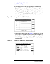
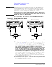
signal is reflected. When a device is frequency swept, a graph similar to
Figure 4-14 on page 95 is obtained. This is an example of a radio
transmitting at a particular frequency. It can be seen that the return
loss at that frequency is a very large number which tapers off to small
return losses at all other frequencies.
Another way of looking at the same information is the SWR (also
known as VSWR: Voltage Standing Wave Ratio). VSWR is stated as a
ratio. For example: 1.2:1 or “one point two to one” VSWR. The first
number in the ratio is a value between 1 and infinity. 1 indicates that
none of the incident wave is reflected. Infinity implies that all of the
incident wave is reflected. Therefore, the closer this number is to 1, the
better the feedline system performance. The second number in the ratio
is always one.
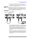
Making the Measurement
NOTE
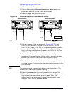
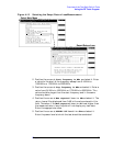
When testing antennas or cables with antennas attached to them, a test
signal is radiated. Verify that the level and frequency span used for the
test cannot result in interference to other nearby systems. To minimize
interference when running the program, set the power level at the
DUPLEX OUT port to the minimum value needed for good
measurement resolution. Set the frequency range carefully.
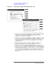
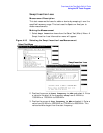
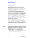
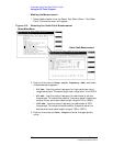
1. Select Swept Return Loss from the Select Test (Main) Menu. The
Swept Return Loss Information menu will appear.