


256 Chapter 8
C:\Spk\Ref\RefGuideRevE\Enc-dec.fm
Signaling Encoder and Decoder - Screens and Control Fields
AMPS-TACS, NAMPS-NTACS Encoder and Decoder
NAMPS-NTACS Reverse Voice Channel Measurements
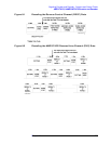
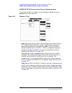
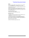
Three types of RVC information can be decoded; selected using the
Measure field. See Figure 8-3.
Figure 8-3 Measure Field
• DSAT displays the 6-digit DSAT (Digital Supervisory Audio Tone) or
DST (Digital Signaling Tone) number, depending on the type of
signal being received. If the received number is not one of the 14
standard combinations (7 DSAT or 7 DST), the decoder displays a
constantly changing number until one of the standard values is
detected. See Figure 8-4 on page 257.
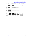
Data displays the 36 message bits and 12 parity bits of the RVC
message. The measurement begins when the last sync word bit is
received, and ends after the last parity bit is received. The
measurement is re-triggered when the next sync word is received:
there is no gate time function for this decoder mode. See Figure 8-4
on page 257.
DTMF displays Dual-Tone Multi-Frequency tone pair frequencies and
on/off times. These are tones that may be used to trigger connected
equipment after a mobile-to-base station connection has been made
(such as an answering machine or voice-mail system). See Figure 8-4
on page 257.