


272 Chapter 8
C:\Spk\Ref\RefGuideRevE\Enc-dec.fm
Signaling Encoder and Decoder - Screens and Control Fields
Control Fields for the Signaling Encoder and Decoder
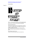
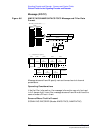
On Time
For the encoder, this field sets the length of time each DTMF tone is on
during the sequence.
For the decoder, this measurement column lists the length of time each
tone is on during the sequence.
Screens Where Field is Present
SIGNALING ENCODER (Modes: DTMF)
SIGNALING DECODER (Modes: DTMF)
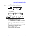
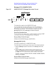
Polarity
This field is used to match the polarity of the encoded signal being
analyzed.
This function is helpful to restore the proper data polarity when the
transmitter, repeater, or receiver used in your communications system
has an odd number of inversions; causing the received data to be
inverted when decoded. (This is common when a signal is translated to
a lower frequency using an LO whose frequency is higher than the
signal’s frequency; or when inverting amplifiers are used.)
Normal Operation
When this field is set to Norm, a logical high (1) is displayed when a
positive peak in the received signal is detected. A negative peak
displays a logical low (0).
Inverted Operation
When this field is set to Invert, a logical low (0) is displayed when a
positive peak in the received signal is detected. A negative peak
displays a logical high (1).
Operating Considerations
Inverting amplifiers used in transmitters, receivers, and repeaters can
cause an inversion of the modulating digital data. If the decoded signal
does not display the expected results, change this field’s setting to see if
the signal may be getting inverted before being decoded.
Screens Where Field is Present
SIGNALING DECODER (Modes: AMPS-TACS, NAMP-NTAC)
SIGNALING ENCODER (Modes: AMPS-TACS, NAMP-NTAC)