


Chapter 4 99
Overview of the Test Set’s Built-In Tools
Using the RF Tools Program
NOTE
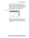
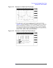
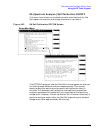
The greatest accuracy is obtained when you enter a cable length
slightly greater than the cable length begin tested. If you are not sure of
the cable length, enter a value 1.5 times the estimated length.
Depending on the return loss of the antenna or device at the end of the
cable, you may see a high relative mismatch displayed at the actual
length of the cable. For example, a 50 foot cable was tested to generate
the plot in Figure 4-18 on page 101.
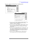
4. Position the cursor at Cable length units. Pressing the knob
toggles the selection between feet and meters.
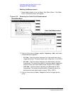
5. Position the cursor at Cable class and select it. A Choices menu
appears allowing selection of Heliax, RG, and custom options. Select
the appropriate cable class. (They can also be selected by pressing
k1
(HELIAX),
k3
(RG), or
k5
(Custom).
6. The next menu varies depending on Cable class:
•If Heliax is selected: Position the cursor at Cable type and
select. A Choices menu appears with foam, air, and flex of
varying thickness. Use the knob to select the desired cable type.
•If RG is selected: Position the cursor at Cable type with the
example [RG 58/U = 58] and select.
•If Custom is selected:
a. Position the cursor at Cable velocity propagation const
and select it. Enter the appropriate value. Cables that use
polyethylene dielectric typically have a propagation velocity of
0.66, cables that use a teflon dielectric typically have a
propagation velocity of 0.70. The propagation velocity must be
a value between 0 and 1.
b. Position the cursor at Cable atten. dB/100 ft. (or
meters) at 500 MHz and select it.
c. If the cable attenuation is unknown, enter 0 dB per 100 feet (or
meters). Entering 0 dB/100 will produce return loss values
lower than actual, but fault distance can be accurately
detected.
7. Press
k1
(Begin Tst).