


90 Chapter 4
C:\Spk\Ref\RefGuideRevE\Tools.fm
Overview of the Test Set’s Built-In Tools
Using the RF Tools Program
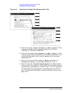
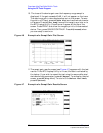
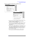
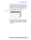
4. Position the cursor at Max expected loss in dB and enter the
greatest loss expected through your device. The insertion loss will be
displayed from 0 dB to the value entered in this field. Therefore, if
the Max expected loss in dB is set higher than the measured
insertion loss, the plot will not display any test data. Enter the
appropriate value.
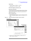
5. Position the cursor at DUPLEX OUT level in dBm and enter the
appropriate value. Unless you are measuring loss through a power
sensitive device, the default level should work correctly.
6. Press
k1
(Begin Tst) to begin the test.
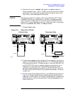
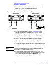
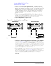
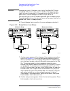
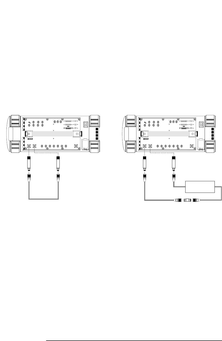
Figure 4-11 Swept Insertion Loss Setups
7. A calibration setup screen appears with a diagram of the necessary
connections (Figure 4-11). This test requires two 6-dB pads. The
pads are put on the ANT IN and DUPLEX OUT ports on the Test Set
to reduce impedance mismatch error at these ports. A reference level
is obtained by connecting a short calibration cable between the pads
on the DUPLEX OUT an ANT IN ports. Setup the hardware, then
press
k1
(Proceed) or the knob to continue.
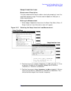
8. After the Test Set has finished calibrating, a second diagram similar
to the Measurement Setup of Figure 4-11 appears on the screen.
Connect the test cable or device to be tested between the calibration
cable and one of the pads. Press
k1
(Proceed) or the knob to
continue.
PARALLEL PORT 15
AUDIO OUT
ANALOG
MODULATION
IN
AUDIO IN
SCOPE
MONITOR
OUT
EXT SCOPE
TRIG IN
VIDEO
OUT
ANT IN DUPLEX OUT
CHIP CLOCK
1.2288
MHz OUT
FRAME
CLOCK
OUT
EVEN
SECOND
SYNC IN
TRIGGER
QUALIFIER
IN
10 MHz
REF OUT
EXT
REF IN
RF IN/OUT
IN
BASEBAND OUT
HI
LO
QI
PARALLEL PORT 16
SERIAL 9
SERIAL 10
SERIAL 11
16X
CHIP CLOCK
19.6608
MHz OUT
DATA
8935
DUPLEX OUT
ANT IN
6dB Pad
Cal Cable
6dB Pad
Calibration Setup
PARALLEL PORT 15
AUDIO OUT
ANALOG
MODULATION
IN
AUDIO IN
SCOPE
MONITOR
OUT
EXT SCOPE
TRIG IN
VIDEO
OUT
ANT IN DUPLEX OUT
CHIP CLOCK
1.2288
MHz OUT
FRAME
CLOCK
OUT
EVEN
SECOND
SYNC IN
TRIGGER
QUALIFIER
IN
10 MHz
REF OUT
EXT
REF IN
RF IN/OUT
IN
BASEBAND OUT
HI
LO
QI
PARALLEL PORT 16
SERIAL 9
SERIAL 10
SERIAL 11
16X
CHIP CLOCK
19.6608
MHz OUT
DATA
8935
DUPLEX OUT
ANT IN
6dB Pad
Cal Cable
Barrel
Connector
6dB Pad
Measurement Setup
s
weptg.eps
Test Cable
or Device