


NDA-24300 CHAPTER 3
Page 157
Issue 1
SYSTEM MESSAGES
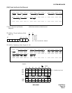
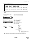
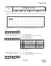
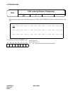
This message displays when the MB switch on the PLO card is turned off while extracting or inserting a circuit
card
.
➀
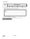
Faulty PLO card No.
➁
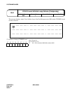
Status of PLO card at the time of
failure detection (Scan Data 1)
➂
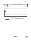
Status of PLO card at the time of
failure detection (Scan Data 2)
1: XXXX XX00 0000 0000 2: 0000 0000 0000 0000 3: 0000 0000 0000 0000
➀ ➁ ➂
4: 0000 0000 0000 0000 5: 0000 0000 0000 0000 6: 0000 0000 0000 0000
7: 0000 0000 0000 0000 8: 0000 0000 0000 0000 9: 0000 0000 0000 0000
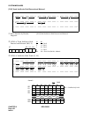
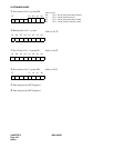
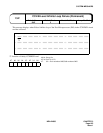
b7 b0
b7 b6 b5 b4 b3 b2 b1 b0
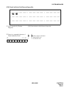
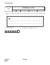
b7 b4 b1 b0
Default Alarm:
NON
7-V
PLO MB Key Turn OFF
Default Grade:
3
Grade Modified: Lamp Modified:
b0: 0/1 = PLO No. 0 system/PLO No. 1 system
b0: 0/1 = Clock STBY/ACT
b1: 0/1 = PLO Synchronizing/PLO self-running or drifting
b2: 0/1 = -/Input clock down
b3, b4:Route of Input clock (see table)
b5: 0/1 = -/PLO input all down
b6: 0/1 = -/PLO output down
b7: 0/1 = -/Drifting
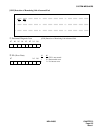
b4 b3
Connected With Primary
Oscillator (M-OSC)
Connected With
External Clock
0 0 NO. 0 M-OSC Route 0
0 1 NO. 1 M-OSC Route 1
10 - Route 2
11 - Route 3
b0: 0/1 = -/n × 5msec clock down
b1: 0/1 = -/Frame Synchronization down from SYNC card
b4: 0/1 = -/Internal OSC clock down