


CHAPTER 4 NDA-24300
Page 266
Issue 1
UNIT/CIRCUIT CARD REPLACEMENT PROCEDURE
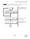
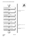
2. TSWM ACCOMMODATING CIRCUIT CARD REPLACEMENT PROCEDURE
This section explains the procedure for replacing circuit cards accommodated in the TSWM.
2.1 Precaution
• This procedure is applied when replacing a faulty circuit card with a spare. It is also able to be applied
when checking a spare card.
• There are the functional switches (having set the default switch) on some of the circuit cards to be
replaced. As for switch setting on the circuit cards, confirm the circuit card mounting face layout for
the PIM. When a circuit card that has default switch settings has been replaced with a spare card, be
sure to make switch settings on the new circuit card the same as on the replaced card. Otherwise, elec-
tronic components on the circuit card may be destroyed, or the circuit card itself may fail to function
normally.
• When handling a circuit card, be sure to use the field service kit for countermeasures against static
electricity. If you touch a circuit card without using the field service kit, electronic components like
an IC on the card may be destroyed by the static electricity on the human body.
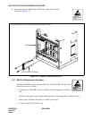
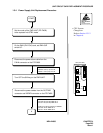
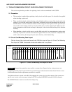
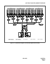
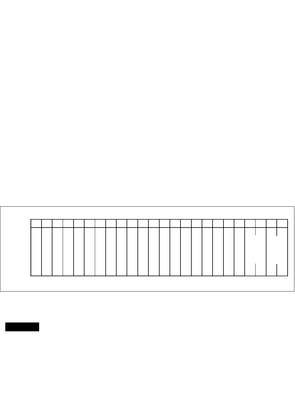
2.2 Circuit Card Mounting Face Layout
The face layout of the circuit cards housed in the TSWM is shown in Figure 4-4 Circuit Card Mounting
Face Layout of TSWM. Note that the circuit cards marked with * are optional.
Figure 4-14 Circuit Card Mounting Face Layout of TSWM
0 0102030405060708091011121314151617181920212223
MISC
MISC
MISC
MISC
DLKC0
DLKC1
GT0
GT1
TSW00
TSW01
TSW02
TSW03
TSW10
TSW11
TSW12
TSW13
(RES)
PWR SW0
TSWM
Slot No.
PWR SW1
MISC
PLO0
PLO1
(RES)
PWRSW: PH-PW14 DLKC: PH-PC20 GT: PH-GT09 TSW: PH-SW12 PLO: PH-CK16/17
*
*
*
*
*
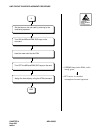
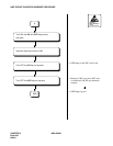
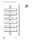
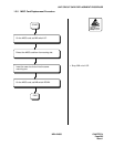
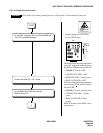
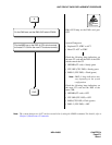
Improper key operations may result in a system down. Operate the key, using extreme care.
By replacing a circuit card, the system will issue system messages and activate the related alarm. Be sure to reset
the indicated alarm after the replacement procedure is complete.
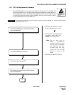
If the indicated alarm is cleared via the RALM command, the system also clears the contents of the system mes-
sage. Be sure to print out the messages (using the DFTD command) BEFORE using the RALM command.
The ALM RST button is used to reset the alarm lamps only.
WARNING