


CHAPTER 5 NDA-24300
Page 374
Issue 1
FAULT REPAIR PROCEDURES
9. FAN UNIT FAULT
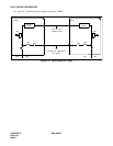
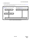
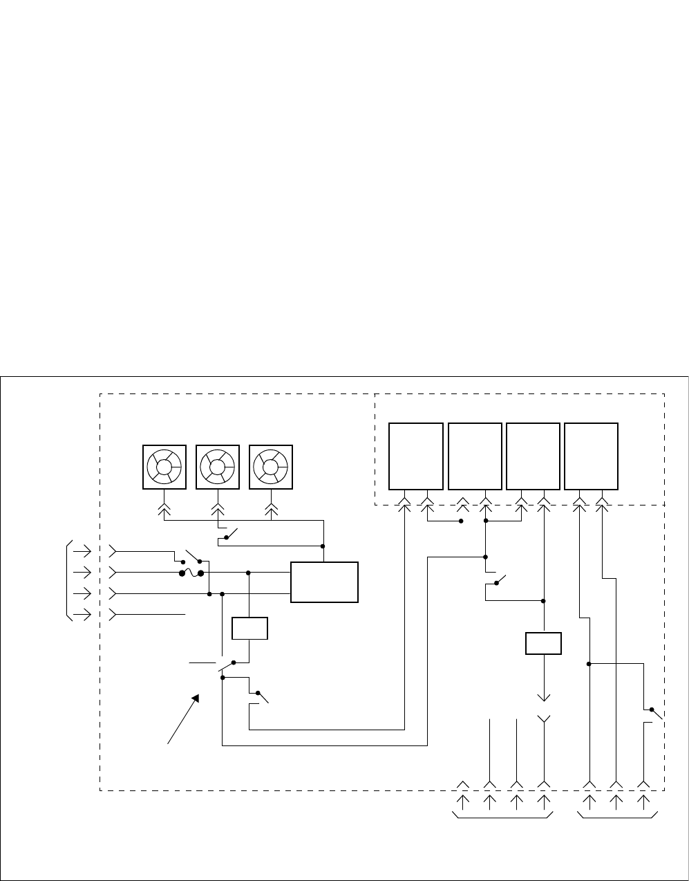
This section explains the fault repair procedure where a fan in the Fan Unit (FANU) does not operate.
9.1 Check Point
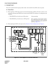
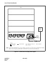
(1) When repairing a FANU fault, exercise care about the following conditions. The fans (a total of 3) are
activated by operating the PWR SW key located on the PZ-M369. The conditions for starting the fan are
as follows:
• With PWR SW key for the fan set to ON position: Always operating
• With PWR SW key for the fan set to AUTO position: Starts operating if the in-frame tempera-
ture is higher than 40°C (104°F); stops op-
erating at temperatures lower than 32°C
(90°F). See Figure 5-19.
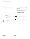
(2) When replacing the FANU with a spare, refer to Section 4., Fan Unit Replacement, in Chapter 4.
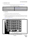
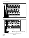
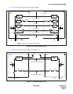
Figure 5-19 Circuit Diagram of Fan Unit and Thermal Unit
FAN 0 FAN 1 FAN 2
Power
Filter
Fan Unit
FC0 FC1 FC2
POW
RL
FUSE ALM
-48V
G
FE
FUSE
FAN
1
3
4
2
To PIM
ON
OFF
AUTO
rl
F
FAN START Switch
Thermal Unit
Thermal
Relay
32
o
C
89
o
F
Thermal
Relay
40
o
C
104
o
F
Thermal
Relay
70
o
C
158
o
F
Thermal
Relay
60
o
C
140
o
F
RL
rl
G FE
FA
LM
FAN
N
P
-48V
EMNMJ
rl
To PIM To Display
Section
of TOPU