


NDA-24300 CHAPTER 3
Page 61
Issue 1
SYSTEM MESSAGES
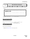
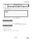
This message displays when the system detects all the failures concerned with input clock down or output clock
down in the PLO card at the ACT side. When this message is indicated, the PLO card changeover executes.
Note:
The No. 0 PLO card automatically changes over to No. 1. The changeover of No. 1 to No. 0 is not
automatic.
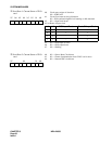
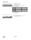
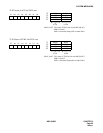
➀
Self-CPU Restart Information
➁
Valid Information bit for Scan Data
1
➂
Valid Information bit for Scan Data
2
Reference: See Chapter 4, Section 2.3.2 and Section 2.3.4, for the circuit card replacement procedure.
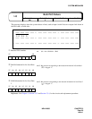
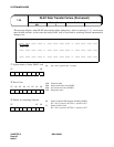
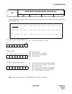
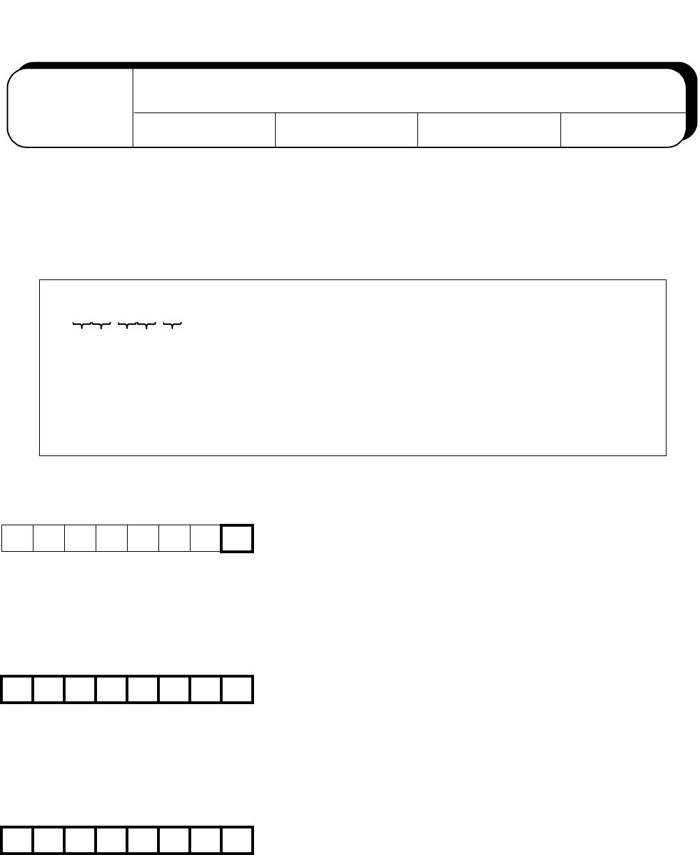
1: XXXX XXXX XX00 0000 2: 0000 0000 0000 0000 3: 0000 0000 0000 0000
➀ ➁ ➂ ➃ ➄
4: 0000 0000 0000 0000 5: 0000 0000 0000 0000 6: 0000 0000 0000 0000
7: 0000 0000 0000 0000 8: 0000 0000 0000 0000 9: 0000 0000 0000 0000
b7 b0
b7 b6 b5 b4 b3 b2 b1 b0
b7 b6 b5 b4 b3 b2 b1 b0
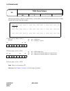
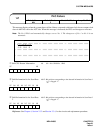
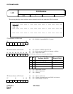
Default Alarm:
MN
1-P
PLO Failure
Default Grade:
3
Grade Modified: Lamp Modified:
b0: 0/1 = No. 0 PLO/No. 1 PLO
b0-b7: Bit position corresponding to the detected information in Scan Data 1
( ) is flagged “1”.
➃
b0-b7: Bit position corresponding to the detected information in Scan Data 2
( ) is flagged “1”.
➄