


NDA-24300 CHAPTER 6
Page 465
Issue 1
SYSTEM OPERATIONS
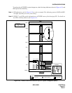
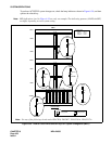
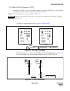
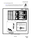
12.1.4 Forced Changeover of CPU
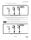
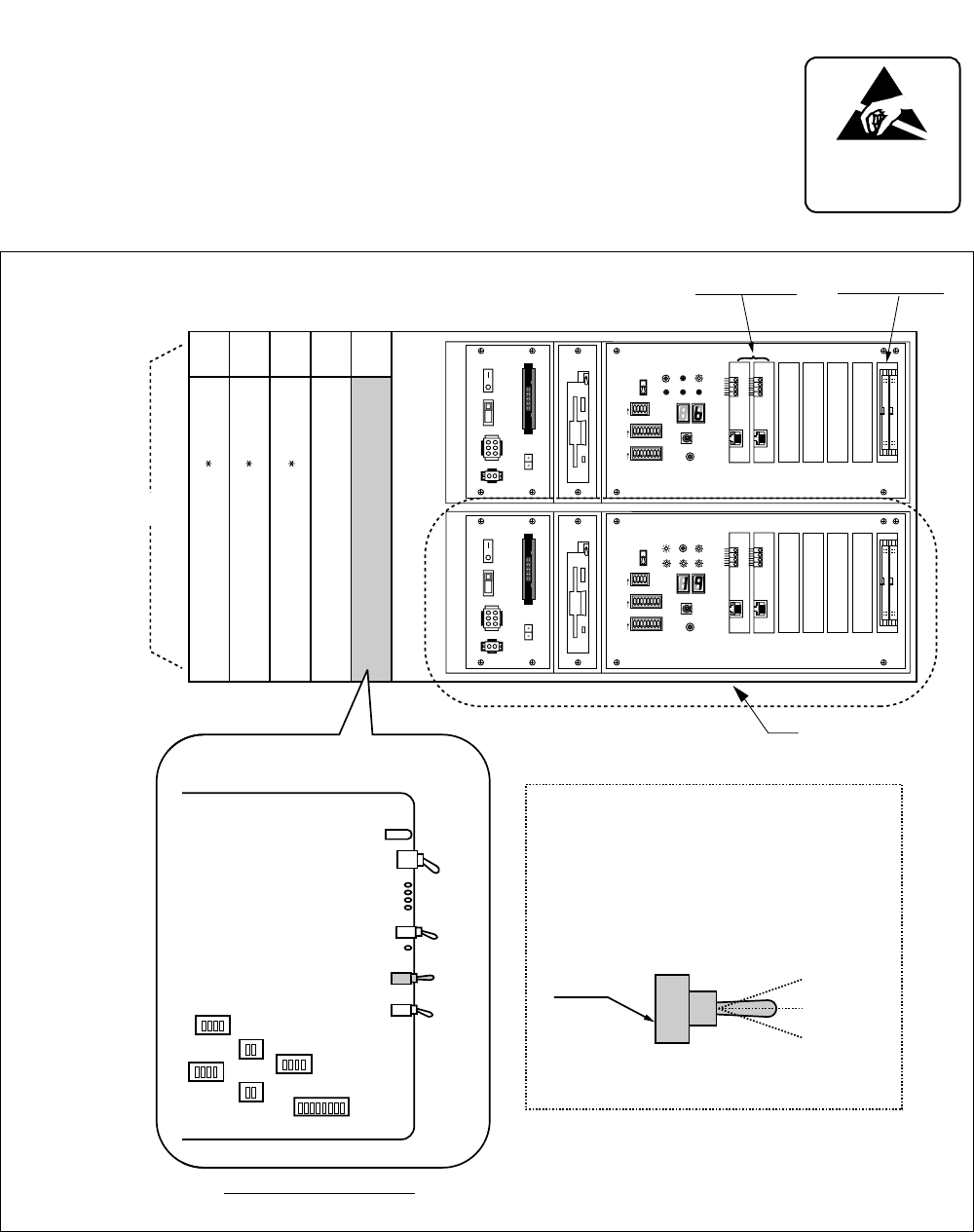
Figure 6-47 shows how to perform the forced changeover of CPU by key oper-
ation on the EMA (PH-PC40) card. Because the key operation will cause the en-
tire system to initialize, do not rely on this method except as a last resort.
Figure 6-47 Forced CPU Changeover
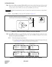
ATTENTION
Contents
Static Sensitive
Handling
Precautions Required
1
2
3
4
5
6
7
8
OFF
1
2
3
4
5
6
7
8
OFF
1
2
3
4
OFF
MBR
FDD
ON
OFF
ON
OFF
OUT PWR
IN PWR
5A
HDD
SW
MB
SYSTEM SELECT0
SENSE
SYSTEM SELECT1
SYSTEM SELECT2
CPURST
SLOT No. 0 1 2 3 4 5 6
STATUS
IMG1 IMG2 IMG3
CPUOPE
WDT
IMG0
ON
ON
ON
4
C
0
2
6
A
E
1
2
3
4
5
6
7
8
OFF
1
2
3
4
5
6
7
8
OFF
1
2
3
4
OFF
MBR
FDD
ON
OFF
ON
OFF
OUT PWR
IN PWR
5A
HDD
SW
MB
SYSTEM SELECT0
SENSE
SYSTEM SELECT1
SYSTEM SELECT2
CPURST
SLOT No. 0 1 2 3 4 5 6
STATUS
IMG1 IMG2 IMG3
CPUOPE
WDT
IMG0
ON
ON
ON
4
C
0
2
6
A
E
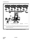
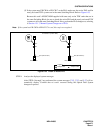
00 01 02 03 04
MISC
MISC/IOC
IOC(PH-IO24)
EMA(PH-PC40)
MISC
LPM
CPR
LANI(PZ-PC19)
ISAGT(PZ-GT13)
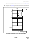
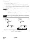
For the forced system changeover, set the CPU-SEL
switch from middle to Up or Down. Note this operation
also leads to system initialization.
1) UP
2) MIDDLE
3) DOWN
For more information, see the Circuit Card Manual.
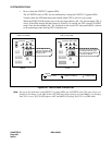
: The CPU#1 is placed into the ACT-side.
: Normal setting for dual CPU configuration.
: The CPU#0 is placed into the ACT-side.
(This setting is mandatory for single CPU
system.)
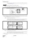
UP
MIDDLE
DOWN
CPU-SEL Key
SW A0
SW92
SW73
SW70
SW62
SW65
OPE/MB
MB
ACT1
CKERR1
ACT0
CKERR0
EMASUP
EMASUP
CPU SEL
NMI SEL
CPU-SEL
EMA(PH-PC40) FACE LAYOUT