


LIST OF FIGURES NDA-24300
Page xii
Issue 1
LIST OF FIGURES (CONTINUED)
Figure Title Page
Figure 6-16 Message Format for Station-to-Station Call . . . . . . . . . . . . . . . . . . . . . . . . . . . . . . . . . . . . . . . 408
Figure 6-17 Message Format for Outgoing Call - Fusion . . . . . . . . . . . . . . . . . . . . . . . . . . . . . . . . . . . . . . 417
Figure 6-18 Message Format for Incoming Call - Fusion . . . . . . . . . . . . . . . . . . . . . . . . . . . . . . . . . . . . . . 418
Figure 6-19 Message Format for Station-to-Station Call - Fusion . . . . . . . . . . . . . . . . . . . . . . . . . . . . . . . . 419
Figure 6-20 SMDR—TCP/IP Interface Billing Output Devices . . . . . . . . . . . . . . . . . . . . . . . . . . . . . . . . . . 423
Figure 6-21 IPX “MAT Menu” Display Image (Example) . . . . . . . . . . . . . . . . . . . . . . . . . . . . . . . . . . . . . . . 428
Figure 6-22 DTFD Command Display Image (Example). . . . . . . . . . . . . . . . . . . . . . . . . . . . . . . . . . . . . . . 430
Figure 6-23 “Listup Report” Window when “View Database” is Selected (Example) . . . . . . . . . . . . . . . . . 431
Figure 6-24 “Export” Dialog for Traffic Report Text File Saving . . . . . . . . . . . . . . . . . . . . . . . . . . . . . . . . . 431
Figure 6-25 Office Data Change Procedure (for Release 1 or 2) . . . . . . . . . . . . . . . . . . . . . . . . . . . . . . . . 434
Figure 6-26 Office Data Change Procedure (for Release 3 or Later) . . . . . . . . . . . . . . . . . . . . . . . . . . . . . 435
Figure 6-27 Backup Commands . . . . . . . . . . . . . . . . . . . . . . . . . . . . . . . . . . . . . . . . . . . . . . . . . . . . . . . . . 436
Figure 6-28 Test Operation Method Examples . . . . . . . . . . . . . . . . . . . . . . . . . . . . . . . . . . . . . . . . . . . . . . 438
Figure 6-29 Register Test Procedure/Connection Diagram . . . . . . . . . . . . . . . . . . . . . . . . . . . . . . . . . . . . 440
Figure 6-30 Sender Test Procedure/Connection Diagram . . . . . . . . . . . . . . . . . . . . . . . . . . . . . . . . . . . . . 441
Figure 6-31 3-Party Conference Test Procedure . . . . . . . . . . . . . . . . . . . . . . . . . . . . . . . . . . . . . . . . . . . . 442
Figure 6-32 3-Party Conference Test Connection Diagram . . . . . . . . . . . . . . . . . . . . . . . . . . . . . . . . . . . . 443
Figure 6-33 Tone Test Procedure/Connection Diagram . . . . . . . . . . . . . . . . . . . . . . . . . . . . . . . . . . . . . . . 444
Figure 6-34 Interrupt Ringing (IR) Test Procedure/Connection Diagram . . . . . . . . . . . . . . . . . . . . . . . . . . 446
Figure 6-35 Trunk Test Procedure . . . . . . . . . . . . . . . . . . . . . . . . . . . . . . . . . . . . . . . . . . . . . . . . . . . . . . . 447
Figure 6-36 Trunk Test Connection Diagram . . . . . . . . . . . . . . . . . . . . . . . . . . . . . . . . . . . . . . . . . . . . . . . 448
Figure 6-37 Switching Network General Block Diagram . . . . . . . . . . . . . . . . . . . . . . . . . . . . . . . . . . . . . . . 456
Figure 6-38 How to Check LEDs and SW Keys for System Changeover (IMG0). . . . . . . . . . . . . . . . . . . . 457
Figure 6-39 How to Check LEDs and SW Keys for System Changeover (IMG1). . . . . . . . . . . . . . . . . . . . 458
Figure 6-40 How to Check LEDs and SW Keys for System Changeover (IMG2/3) . . . . . . . . . . . . . . . . . . 459
Figure 6-41 How to Check STATUS LEDs . . . . . . . . . . . . . . . . . . . . . . . . . . . . . . . . . . . . . . . . . . . . . . . . . 460
Figure 6-42 System Block Diagram (Switching Network Between CPU and GT) . . . . . . . . . . . . . . . . . . . . 462
Figure 6-43 CPU in ACT/STBY Mode . . . . . . . . . . . . . . . . . . . . . . . . . . . . . . . . . . . . . . . . . . . . . . . . . . . . . 463
Figure 6-44 GT in ACT/STBY Mode . . . . . . . . . . . . . . . . . . . . . . . . . . . . . . . . . . . . . . . . . . . . . . . . . . . . . . 463
Figure 6-45 CPU Changeover via MBR Key. . . . . . . . . . . . . . . . . . . . . . . . . . . . . . . . . . . . . . . . . . . . . . . . 464
Figure 6-46 LED Indications Before and After CPU Changeover . . . . . . . . . . . . . . . . . . . . . . . . . . . . . . . . 464
Figure 6-47 Forced CPU Changeover. . . . . . . . . . . . . . . . . . . . . . . . . . . . . . . . . . . . . . . . . . . . . . . . . . . . . 465
Figure 6-48 System Block Diagram (Switching Network for Speech Path System) . . . . . . . . . . . . . . . . . . 468
Figure 6-49 TSW/DLKC/MUX in ACT Mode . . . . . . . . . . . . . . . . . . . . . . . . . . . . . . . . . . . . . . . . . . . . . . . . 469
Figure 6-50 TSW/DLKC/MUX in STBY Mode . . . . . . . . . . . . . . . . . . . . . . . . . . . . . . . . . . . . . . . . . . . . . . . 469
Figure 6-51 Speech Path System Changeover via Active GT MBR Key . . . . . . . . . . . . . . . . . . . . . . . . . . 470
Figure 6-52 LED Indications Before and After Speech Path System Changeover . . . . . . . . . . . . . . . . . . . 470
Figure 6-53 Check of Active PLO . . . . . . . . . . . . . . . . . . . . . . . . . . . . . . . . . . . . . . . . . . . . . . . . . . . . . . . . 471
Figure 6-54 PLO in ACT/STBY Mode . . . . . . . . . . . . . . . . . . . . . . . . . . . . . . . . . . . . . . . . . . . . . . . . . . . . . 472
Figure 6-55 PLO Changeover via MB Key . . . . . . . . . . . . . . . . . . . . . . . . . . . . . . . . . . . . . . . . . . . . . . . . . 473
Figure 6-56 LED Indications Before and After PLO Changeover . . . . . . . . . . . . . . . . . . . . . . . . . . . . . . . . 473
Figure 6-57 Conceptional Diagram of Initial Program Load . . . . . . . . . . . . . . . . . . . . . . . . . . . . . . . . . . . . 477
Figure 6-58 Related Keys and LEDs for System Initialization. . . . . . . . . . . . . . . . . . . . . . . . . . . . . . . . . . . 478
Figure 6-59 How to Turn ON the Whole System. . . . . . . . . . . . . . . . . . . . . . . . . . . . . . . . . . . . . . . . . . . . . 487
Figure 6-60 How To Turn OFF the Whole System . . . . . . . . . . . . . . . . . . . . . . . . . . . . . . . . . . . . . . . . . . . 488
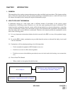
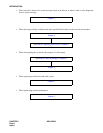
Figure 7-1 Flow of Procedures . . . . . . . . . . . . . . . . . . . . . . . . . . . . . . . . . . . . . . . . . . . . . . . . . . . . . . . . . 495
Figure 7-2 Adjusting Time on ATTCON. . . . . . . . . . . . . . . . . . . . . . . . . . . . . . . . . . . . . . . . . . . . . . . . . . . 507
Figure 7-3 Desk Console. . . . . . . . . . . . . . . . . . . . . . . . . . . . . . . . . . . . . . . . . . . . . . . . . . . . . . . . . . . . . . 508
Figure 8-1 Port Status Report (MG) Display . . . . . . . . . . . . . . . . . . . . . . . . . . . . . . . . . . . . . . . . . . . . . . . 614