


CHAPTER 4 NDA-24300
Page 268
Issue 1
UNIT/CIRCUIT CARD REPLACEMENT PROCEDURE
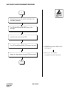
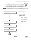
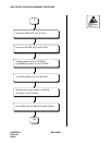
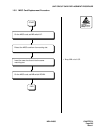
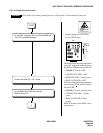
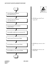
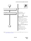
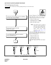
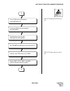
2.3.1 GT Card Replacement Procedure
The GT (PH-GT09) card is located in Slot No. 10 or 11 within the TSWM. The card’s main function
is to provide both MISC and I/O Local bus interface between the microprocessor of CPU and other
lower echelons, such as DLKC, TSW and MUX cards. Follow the procedures below to replace a GT
card with a spare.
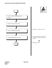
Note:
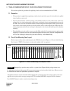
To replace the GT card, the ACT/STBY status of GT must be changed over first. This must be done by
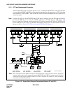
operating the MBR key (or by using the CMOD command) on the DSP of active CPR. Figure 4-15
shows a system block diagram centering upon the CPU and its controlling GT. If the ACT/STBY of GT
is to be changed over, the system of CPU must be manually changed over. For more details on the GT
changeover, refer to Section 12.1.2, How to Control CPU Block, in Chapter 6.
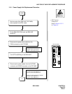
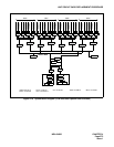
Figure 4-15 System Block Diagram (Connections Between GT and CPU)
IMG0 IMG1 IMG2 IMG3
TSW I/O BUS
TSW I/O BUS
CPR 0
CPR 1
MISC BUS
IOP0
Backboard
Backboard Bus
T
External Cable
TSW 00
GT 0
GT 1
CPU 1
MUX MUX MUX MUX
TSW 10
TSW 01
MUX MUX MUX MUX
TSW 11
TSW 02
MUX MUX MUX MUX
TSW 12
TSW 03
MUX MUX MUX MUX
TSW 13
DLKC 1
DLKC 0
PLO 1
PLO 0
ISAGT
LANI LANI
ISAGT
LANI LANI
IOC/
MISC
EMA
CPU 0
CPU
ISAGT0
GT 1
GT 0
Note:
The connection between ISAGT and GT is somewhat unique in this system. As shown, though an
external cable is physically connected between ISAGT #0 and GT#1, the actual control signal is
sent/received only between ISAGT 0 and GT 0. This is because GT 0 and GT 1 have a multiple
connection on the backboard side.
Note
ISAGT: PZ-GT13 LANI: PZ-PC19 GT: PH-GT09 TSW: PH-SW12 MUX: PH-PC36
DLKC: PH-PC20 PLO: PH-CK16/17 EMA: PH-PC40 IOC: PH-IO24