


NDA-24300 CHAPTER 4
Page 301
Issue 1
UNIT/CIRCUIT CARD REPLACEMENT PROCEDURE
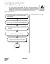
5. CPR Cooling Fan Replacement
This section explains how to replace a cooling fan in the back side of the CPR. This procedure is necessary
when a fault is detected in the cooling fan. Because the fan is a vital device to protect the CPR from heated air,
it is also recommended that the fan be replaced at least every two years, even if a fault is not detected.
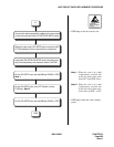
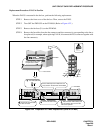
STEP 1 Set the CPU, whose rack houses the fan to be replaced, in STBY mode via the MBR key on
the DSP (Refer to Figure 4-24.)
Note
Note:
For the ACT/STBY changeover of the CPU, see Chapter 6.
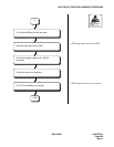
STEP 2 Disconnect the power alarm cable from the PALM connector on PZ-PW92.
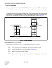
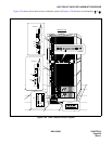
STEP 3 Turn OFF the PWR SW on the PZ-PW92 (Refer to Figure 4-24 Face Layout of CPR.)
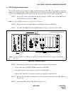
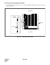
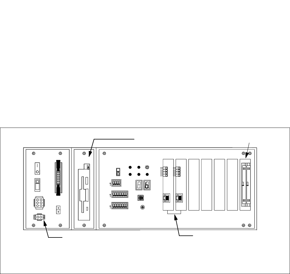
Figure 4-24 CPR Face Layout
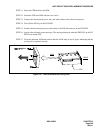
STEP 4 Disconnect the power and bus and ether cables from the relevant connectors.
• Power cables from OUTPWR, INPWR connectors on PZ-PW92
• Bus cables from the front connectors on PZ-GT13 and PZ-GT16
• Ether (UTP CTG5 ST CA-n) cables from the front connectors on the PZ-PC19.
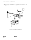
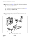
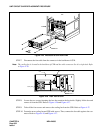
STEP 5 Remove the front bracket, and then take off the four screws fastened onto the CPU. (Refer to
Figure 4-25.)
STEP 6 Extract the CPR from the LPM. (Refer to Figure 4-25.)
Note:
In place of PZ-IO27, the CPR may be equipped with PZ-IO28, which does not have the MB (Make-
busy) key.
1
234
5
678
OFF
12345678
OFF
1234
OFF
MBR
FDD
ON
OFF
ON
OFF
OUT PWR
IN PWR
5A
HDD
SW
MB
SYSTEM SELECT0
SENSE
SYSTEM SELECT1
SYSTEM SELECT2
CPURST
SLOT No. 0 1 2 3 4 5 6
STATUS
IMG1 IMG2 IMG3
CPUOPE WDT IMG0
ON
ON
ON
4
C
0
2
6
A
E
PZ-IO27
PZ-PW92
PZ-PC19 (LANI)
PZ-GT16 and PZ-GT13 (ISAGT)
PALM
Note