


NDA-24300 CHAPTER 6
Page 487
Issue 1
SYSTEM OPERATIONS
12.3 How to Turn ON/OFF Whole System
A switching system, once put into service, is seldom stopped. However, there may be a case when a
switching system must be stopped due to module expansion work, etc. In preparation for such a case, this
section explains the procedure for stopping the system and turning ON the power supply.
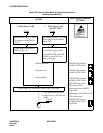
12.3.1 How to Turn On Whole System
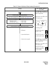
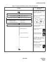
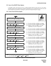
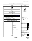
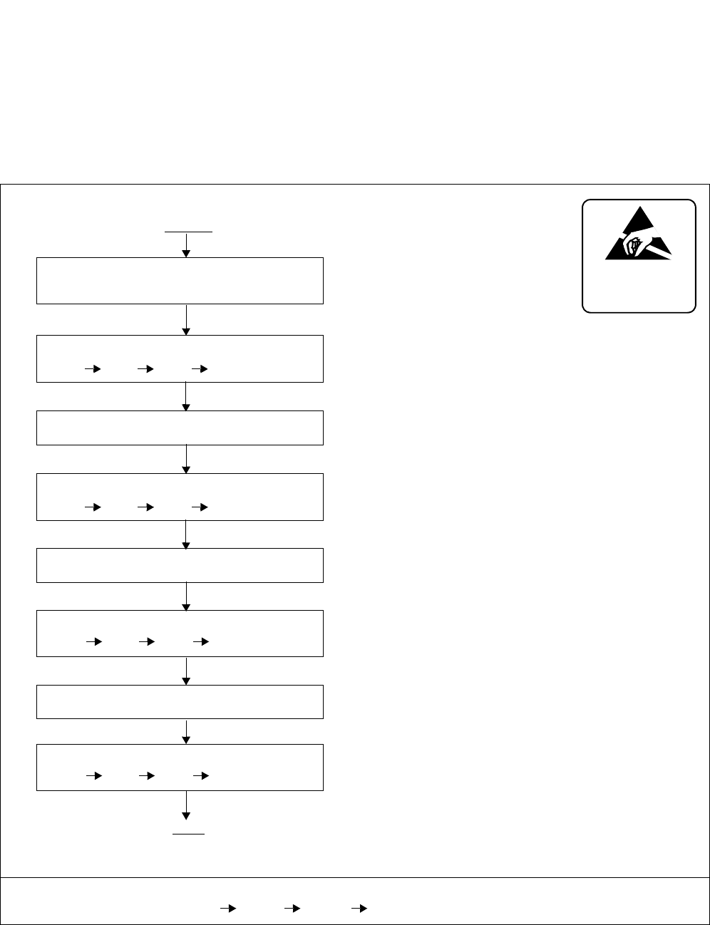
Figure 6-59 How to Turn ON the Whole System
Note:
Start from bigger number depending on configuration of IMG stack.
(i.e. 1.5 stack: IMG3 IMG2 IMG1 IMG0).
Confirm SENSE switch on DSP of Active
CPU is set at 2 (DM Load Restart).
START
Turn ON power supply at PIMs of IMG3.
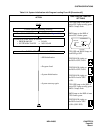
Turn ON power supply at TSWM0.
Turn ON power supply at LPM.
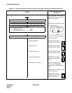
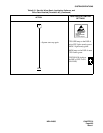
END
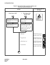
Turn ON power supply at PIMs of IMG0.
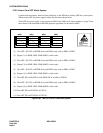
PIM0 PIM1 PIM2 PIM3
PIM0 PIM1 PIM2 PIM3
Turn ON power supply at TSWM1.
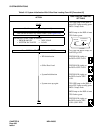
Turn ON power supply at PIMs of IMG2.
PIM0 PIM1 PIM2 PIM3
Turn ON power supply at PIMs of IMG1.
PIM0 PIM1 PIM2 PIM3
ATTENTION
Contents
Static Sensitive
Handling
Precautions Required
(1) Turn ON -48V SW on PWR card in PIM0.
(2) Turn ON -48V SW on DPWR card in PIM0.
(3) Repeat (1) and (2) for PIM1, 2, 3 in turn
(depending on system configuration).
(1) Turn ON -48V SW on PH-PW14 (PWR SW#0).
(2) Turn ON -48V SW on PH-PW14 (PWR SW#1).
(1) Turn ON -48V SW on PWR card in PIM0.
(2) Turn ON -48V SW on DPWR card in PIM0.
(3) Repeat (1) and (2) for PIM1, 2, 3 in turn
(depending on system configuration).
(1) Turn ON -48V SW on PH-PW14 (PWR SW#0).
(2) Turn ON -48V SW on PH-PW14 (PWR SW#1).
(1) Turn ON -48V SW on PWR card in PIM0.
(2) Turn ON -48V SW on DPWR card in PIM0.
(3) Repeat (1) and (2) for PIM1, 2, 3 in turn
(depending on system configuration).
(1) Turn ON the SW on PZ-PW92 CPU #0.
(2) Turn ON the SW on PZ-PW92 CPU #1.
(1) Turn ON -48V SW on PWR card in PIM0.
(2) Turn ON -48V SW on DPWR card in PIM0.
(3) Repeat (1) and (2) for PIM1, 2, 3 in turn
(depending on system configuration).