


CHAPTER 4 NDA-24300
Page 302
Issue 1
UNIT/CIRCUIT CARD REPLACEMENT PROCEDURE
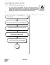
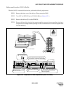
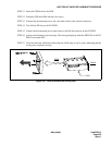
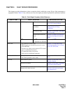
Figure 4-25 Extraction of CPR from LPM
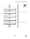
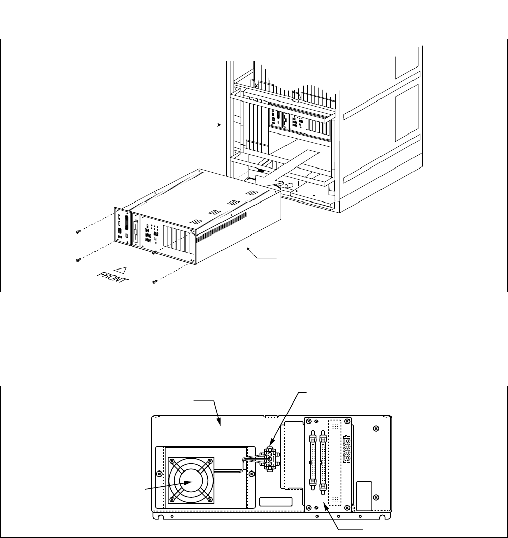
STEP 7 Disconnect the fan cable from the connector in the backbone of CPR.
Note:
The cooling fan is located in the backbone of CPR and the cable connector lies in its right side. Refer
to Figure 4-26.
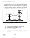
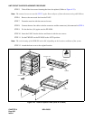
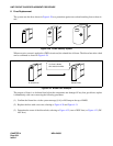
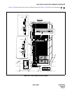
Figure 4-26 Rear View of CPR
STEP 8 Loosen the two screws fastening the box that contains the fan inside. Slightly lift the box and
remove it from the CPR. Refer to Figure 4-26 and Figure 4-27.
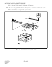
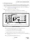
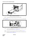
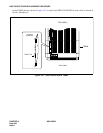
STEP 9 Take off the four screws and remove the cooling fan from the CPR. Refer to Figure 4-27.
STEP 10 Fasten the new cooling fan and CPR with screws. Then, connect the fan cable again to the con-
nector. Refer to Figure 4-26 and Figure 4-27.
..........
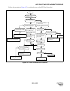
1
2
3
4
5
6
7
8
1
2
3
4
5
6
7
8
1
2
3
4
5
A
SLOT
No. 0 1
23
45
6
2
6
E
..........
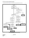
1
2
3
4
5
6
7
8
1
2
3
4
5
6
7
8
1
2
3
4
5A
SLOT No.
0
1
2
3
4
5
6
2
6
E
CPR
LPM
PBX
Connector for Cooling FAN Cable
CPR
PZ-M14
Cooling FAN