


NDA-24300 CHAPTER 5
Page 367
Issue 1
FAULT REPAIR PROCEDURES
8. POWER SUPPLY FAULT
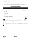
This section explains the fault repair procedure when any of the faults shown in Table 5-10 occur.
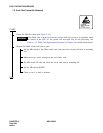
8.1 Check Point
When repairing a power supply fault, consider the following items:
(1) Before checking the system, check the rectifier, battery, and power cables.
(2) The PWR circuit card is equipped with the circuits to supply ringing signal and howler tone. When a fault
occurs that causes the bell of the telephone not to ring, or howler tone cannot be heard, etc., check the
alarm lamp on the PWR circuit card.
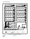
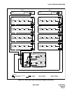
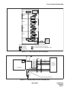
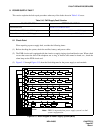
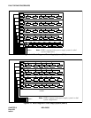
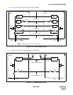
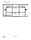
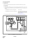
(3) Figure 5-13 through Figure 5-15 show the block diagrams for the power supply to each module.
Figure 5-13 Block Diagram of Power Supply System (IMG0)
Table 5-10 PWR Supply Fault Situation
FAULTY SITUATION REFERENCE SECTION
Fuse Blown Fault Section 8.2, Fuse Blown Fault
Circuit Breaker OFF, Fault in PWR Supply Section 8.3, Circuit Breaker OFF Fault in PWR Supply
Fault of Alarm Lamps on PWR Supply Section 8.4, Fault of Alarm Lamps on PWR Supply
Note:
PWR1 is mounted when power supply system is a dual
system configuration.
PWR
0
PWR
1
LC/TRK
LC/TRK MUX0 MUX1 LC/TRK LC/TRK
PIM3
Note
PWR
0
PWR
1
LC/TRK
LC/TRK MUX0 MUX1 LC/TRK LC/TRK
PIM2
Note
PWR
0
PWR
1
LC/TRK
LC/TRK MUX0 MUX1 LC/TRK LC/TRK
PIM1
Note
PWR
0
PWR
1
LC/TRK
LC/TRK MUX0 MUX1 INT1 LC/TRK
PIM0
Note
PWR
0
PWR
1
EMA
IOC
MISC
LPM
Note
CPU0
ISAGT0
BASEU
IMG0