


CHAPTER 6 NDA-24300
Page 464
Issue 1
SYSTEM OPERATIONS
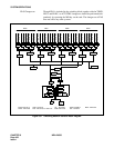
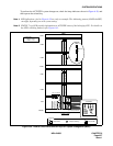
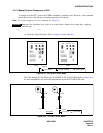
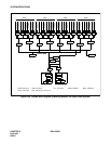
(2) Check the mate CPU’s STBY mode. Also check the mate GT’s STBY mode. Refer to Fig-
ure 6-43 and Figure 6-44.
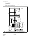
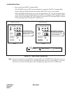
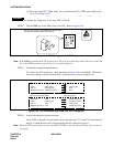
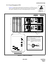
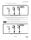
STEP 2 Flip the MBR key on the DSP of the active CPU. Refer to Figure 6-45.
Figure 6-45 CPU Changeover via MBR Key
Note:
If the MBR key remains in the UP position, the CPU stays in its make-busy status. Be sure to return the
key to the DOWN position except in the case of a special purpose.
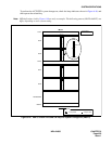
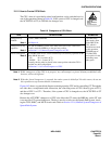
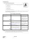
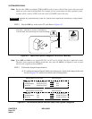
STEP 3 Confirm the changed lamp indications.
To confirm the CPU changeover, check the lamps in Figure 6-46 on both DSPs. LED indica-
tions must change as shown when the CPU system has been correctly changed over.
Figure 6-46 LED Indications Before and After CPU Changeover
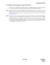
STEP 4 Analyze the displayed system messages.
After STEPs 1 through 3 are performed, the system messages [7-C] and [7-D] automatically
display. Confirm that no errors occurred during the CPU changeover process.
Note:
When the CPU mode change executes, the MAT (TCP/IP) is once disconnected. Then, log in to the sys-
tem again.
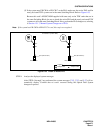
The system changeover of CPU can be done only when the mate CPU is in STBY mode. Do
not attempt the changeover if the mate CPU is closed.
WARNING
After the above steps, set the MBR key as shown below.
The system changeover starts automatically.
1
2
3
4
5
6
7
8
OFF
1
2
3
4
5
6
7
8
OFF
1
2
3
4
OFF
4
C
0
2
6
A
E
1 2
DSP (Active)
STATUS
ATTENTION
Contents
Static Sensitive
Handling
Precautions Required
CPU Formerly Active After Changeover
CPU Formerly in STBY Mode
CPU OPE
IMG0
IMG1-3
MB/OPE (GT Card)
After Changeover
OFF
Flash (green)
OFF
OFF
: Steady-ON (green)
: Flash (green)
: Flash (green)
: Steady-ON (green)
CPU OPE
IMG0
IMG1-3
MB/OPE (GT Card)
Steady-ON (green)
Steady-ON (green)
Flash (green)
Steady-ON (green)
: OFF
: Flash (green)
: OFF
: OFF