


CHAPTER 5 NDA-24300
Page 334
Issue 1
FAULT REPAIR PROCEDURES
4.1 Check Point
When repairing a unit fault, consider the following items:
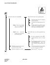
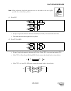
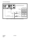
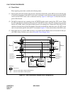
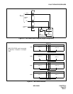
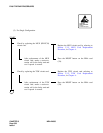
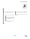
(1) Speech paths and control paths in the unit are connected to line/trunks via the MUX circuit cards. Be sure
to check the alarm lamps on the MUX circuit cards, and check to see if the front cable between each MUX
circuit card and TSW circuit card is connected correctly. Figure 5-5 and Figure 5-6 show the block dia-
gram within the unit.
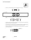
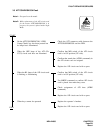
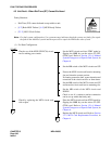
(2) The MUX circuit cards are operating in the ACT/STBY modes under control of the CPU circuit. When
the ACT-side CPU has detected a fault in the ACT-side MUX circuit card, CPU changeover is executed
and the ACT/STBY mode of the Speech Path System is also changed over. When both of the MUX circuit
cards have become faulty, all the lines/trunks in that unit are placed into make-busy state. (If a PFT circuit
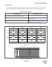
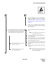
card is located in that specific unit, the PFT is activated.) Figure 5-7 shows the location of the MUX cards.
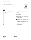
(3) When both units in a specific PIM are faulty, it is possible that the PWR circuit card mounted in that spe-
cific PIM is faulty. In such a case, refer to Section 8, Power Supply Fault.
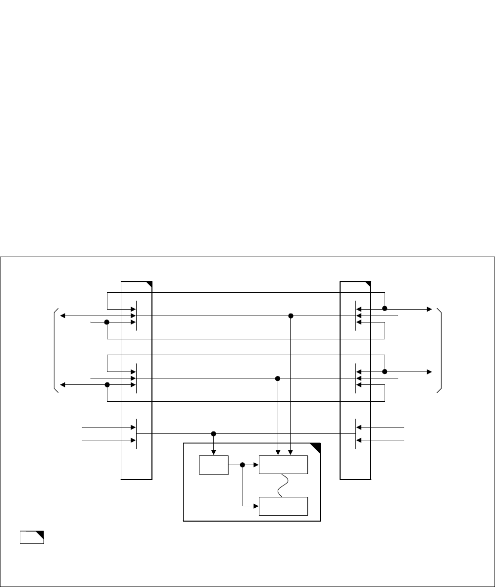
Figure 5-5 Unit Control Block Diagram (Dual Configuration)
MUX0
Clock
(B)
(A)
Speech
Path
To
TSW/INT
MUX1
LC/TRK
LC/TRK
PM
Line/
Trunk
Circuit Card
Control of
CPU No. 0
ACT/STBY of
CPU No. 0
Clock
(B)
Speech
Path
(A)
To
TSW/INT
Control of
CPU No. 1
ACT/STBY of
CPU No. 1
SYMBOLS
: Circuit Card
: Control on ACT/STBY of Speech Path Systems
: Control on ACT/STBY of Clock Systems
(A)
(B)