


NDA-24300 CHAPTER 5
Page 383
Issue 1
FAULT REPAIR PROCEDURES
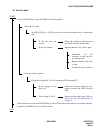
12. COMMON CHANNEL INTEROFFICE SIGNALING (CCIS) LINE FAULT
This section explains the fault repair procedure when any of the faults shown in Table 5-11 occur to a specific
CCIS line.
12.1 Check Point
When repairing a CCIS Line fault, consider the following items:
(1) Check alarm lamps on the CCH or CCT circuit card.
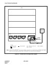
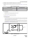
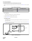
(2) Refer to Figure 5-23, and check the cable connection.
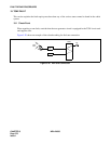
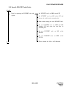
12.2 CCIS Line Control
The CCH/CCT circuit card controls the signal link (digital) of the interoffice common channel signaling
system and transmitting/receiving call processing information. The signal link controls permit normal
transmission and reception of call processing information.
A break in signal links is detected, then restored to establish signal links. The call processing information
is converted into No. 7 signal format for channel 1 (any channel) of the DTI before being transmitted to a
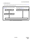
distant office. Figure 5-23 shows the CCIS line control route.
Figure 5-23 Controlling CCIS Line
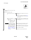
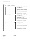
Table 5-11 CCIS Line Fault Situation
FAULTY SITUATION REFERENCE SECTION
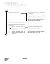
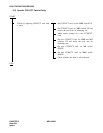
A specific CCH/CCT card is faulty. Section 12.3, Specific CCH/CCT Card Is Faulty
When the signal transmission line is a digital line, transmitting/
receiving of control signals cannot be performed.
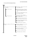
Section 12.4, Fault of CCH, DTI and Related Flat
Cable
CPU TSW
MUX
CCH
CCT
DTI
LT Cable
Front
Cable
MDF
To CCIS Line
LT Cable