


NDA-24300 CHAPTER 6
Page 391
Issue 1
CHAPTER 6 SYSTEM OPERATIONS
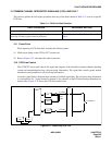
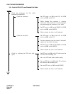
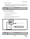
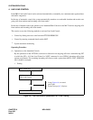
To maintain the system in a normal state, maintenance technicians need to monitor the servicing status of the
system. Figure 6-1 shows the flow of the system status monitor.
When trouble occurs in any part of the system or to any phase of system operations, maintenance technicians
are alerted by an alarm indication or by a report from a station user or an operator. When the system becomes
overloaded, maintenance technicians can execute Line Load Control.
Figure 6-1 System Status Monitor
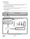
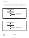
1. ALARM INDICATIONS
When trouble occurs in the system, the system activates an appropriate remedial action (system changeover,
make-busy shift of the circuit card, restart processing, etc.) by executing the automatic diagnostic function. Re-
sults of the action taken and the faulty situation are displayed.
1.1 Kinds of Alarm Indications
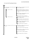
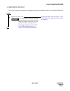
Figure 6-2 shows the kinds of alarm indications.
Figure 6-2 Alarm Indications
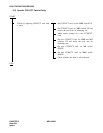
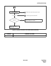
SYSTEM STATUS MONITOR
1. ALARM INDICATIONS
•
Alarm Lamps on Circuit Card
•
Alarm Lamps on TOPU
•
Alarm Lamps on Attendant Console
2. COLLECTION OF SYSTEM MESSAGES
3. INDICATION OF LOCKOUT STATUS
4. LINE LOAD CONTROL
ALARM INDICATIONTROUBLE
SYSTEM MESSAGE
TOPU
CIRCUIT CARDS
ATTENDANT/DESK CONSOLE
MAT
SYSTEM DEDICATED PRINTER