


CHAPTER 6 NDA-24300
Page 478
Issue 1
SYSTEM OPERATIONS
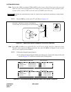
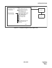
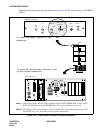
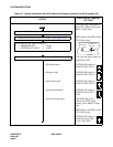
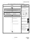
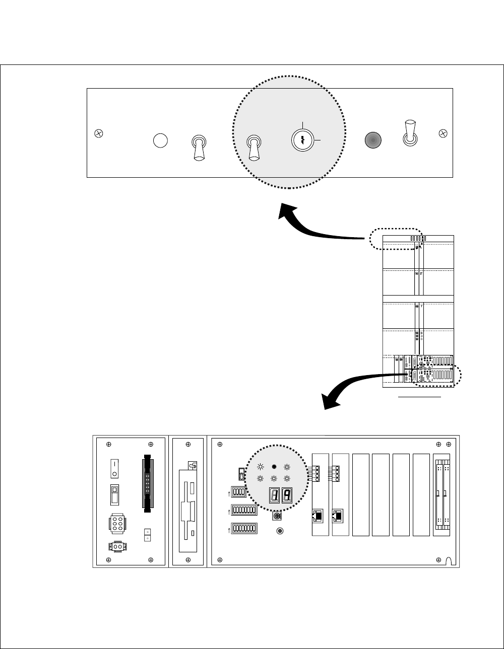
To initialize the system, check the lamp indications in Figure 6-58, and operate the keys on PZ-DK222
(TOPU).
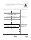
Figure 6-58 Related Keys and LEDs for System Initialization
LOAD
NON LOAD
PROGRM
NON LOAD
SYSTEM DATA
LOAD
1
2
3
4
5
6
7
8
OFF
1
2
3
4
5
6
7
8
OFF
1
2
3
4
OFF
MBR
FDD
ON
OFF
ON
OFF
OUT PWR
IN PWR
5A
HDD
SW
MB
SYSTEM SELECT2
CPURST
SLOT No. 0 1 2 3 4 5 6
ON
ON
ON
ALM
RST
ON
OFF
PFT
ON
OFF
START
INITIAL EFFECT
03
04
13 14
13
14
13 14
13 14
FRONT VIEW
IMG0
..........
..........
1
2
3
4
5
6
7
8
OFF
OFF
1
2
3
4
OFF
1
2
3
4
5
6
7
8
OFF
4
C
0
2
6
A
E
1
2
3
4
5
6
7
8
OFF
OFF
1
2
3
4
OFF
1
2
3
4
5
6
7
8
OFF
4
C
0
2
6
A
E
4
C
0
2
6
A
E
SENSE
SYSTEM SELECT0
SYSTEM SELECT1
STATUS
IMG1 IMG2 IMG3
CPUOPE
WDT
IMG0
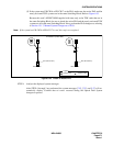
PZ-DK222: Face Layout
CPR: Face Layout
Note 1
Note 2
Note 1:
This figure assumes that the CPR is equipped with PZ-IO27 (HDD/FDD), in place of PZ-
IO28. If PZ-IO28 is used, the MB (Make-busy) key is not furnished on the card.
Note 2:
The LED indication cited above is only an example. The actual indicating patterns (ON/
Flash/OFF) may vary, depending on the system configuration.
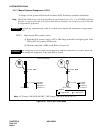
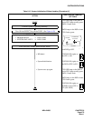
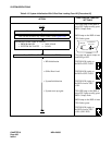
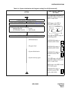
To initialize the system, operate the keys
shaded here.
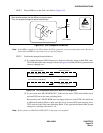
To confirm the imposed system initialization, check
the lamp indicators shaded here.