


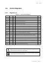
III - 11
Chapter 3 Interrupts
Overview
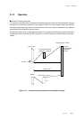
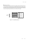
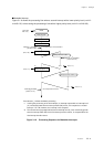
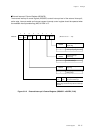
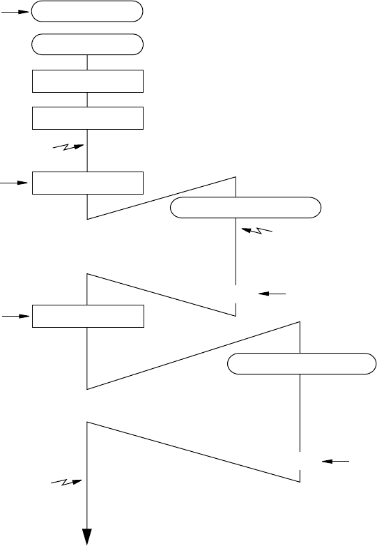
Figure 3-1-6 Processing Sequence for Maskable Interrupts
■Maskable Interrupt
Figure 3-1-6 shows the processing flow when a second interrupt with a lower priority level (xxxLV1-
xxxLV0='10') arrives during the processing of one with a higher priority level (xxxLV1-xxxLV0='00').
Main program
Set MIE
IM1,0='11'
Interrupt service routine: 1
RTI
Interrupt 1 generated
(xxxLV1,0='00')
(IM1,0='00')
Interrupt 2 generated
( xxxLV1,0='10')
*1
Interrupt generated
(xxxLV1,0='11')
(IM1,0='11')
RTI
(IM1,0='10')
Interrupt service routine: 2
(IM1,0='11')
*2
(Clear MIE
IM0,1='00')
Reset
Accepted because IL<IM and MIE='1'
Not accepted because IM=IL
Interrupt acceptance cycle
Interrupt acceptance cycle
Parentheses ( ) indicate hardware processing.
*1 If during the processing of the first interrupt, an interrupt request with an interrupt level
(IL) numerically lower than the interrupt mask (IM) arrives, it is accepted as a nested
interrupt. If IL ≥ IM, however, the interrupt is not accepted.
*2 The second interrupt, postponed because its interrupt level (IL) was numerically greater
than the interrupt mask (IM) for the first interrupt service routine, is accepted when the
first interrupt handler returns.