


I - 19
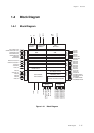
Chapter 1 Overview
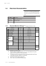
Electrical Characteristics
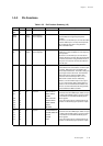
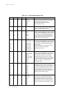
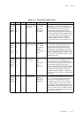
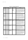
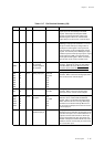
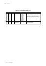
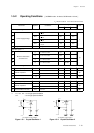
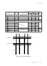
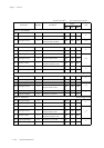
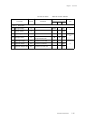
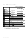
1-5-2 Operating Conditions
*1 tc1, tc2, tc3 : 1/2 of high speed oscillation
tc4 : 1/2 of high speed oscillation
[ NORMAL mode : fs=fosc/2, SLOW mode : fs=fx/2 ]
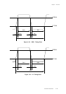
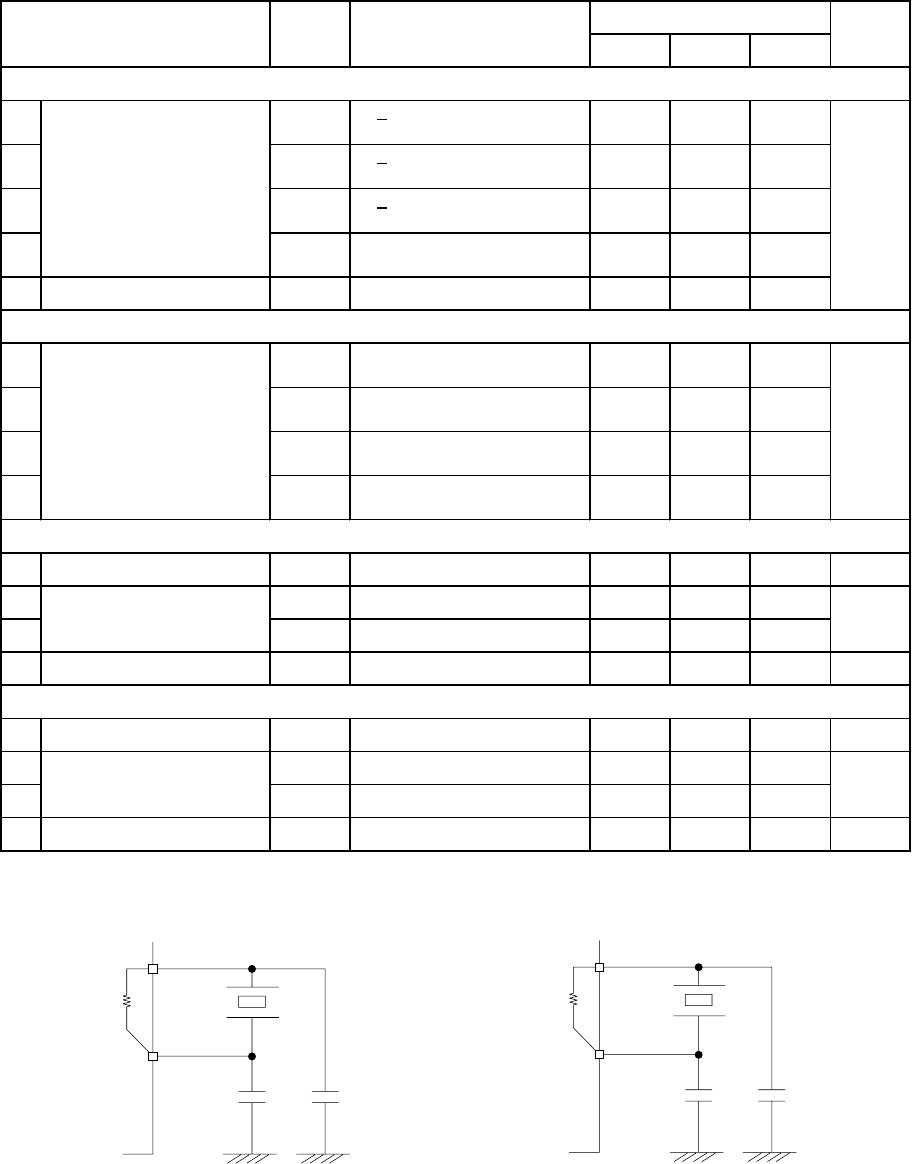
Figure 1-5-1 Crystal Oscillator 1 Figure 1-5-2 Crystal Oscillator 2
OSC1
R
F10
OSC2
MN101C
f
xtal1
C
12
C
11
The feedback resistor is built-in.
XI
XO
MN101C
f
xtal2
C
22
C
21
The feedback resistor is built-in.
RF20
T
a
=-40
o
C to +85
o
C
V
DD
=1.8 V to 3.6 V, V
SS
=0
V
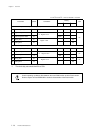
Power supply voltage
f
osc
< 20.00 MHz
f
osc
< 10.00 MHz
f
osc
< 4.00 MHz
fx = 32.768 kHz
5
Operation speed *1
Crystal osillator 1 Figure 1-5-1
10
11
12
13
Crystal osillator 2 Figure 1-5-2
14
15
16
17
f
s
= f
osc
/2
2.1
1.8
1.8
3.6
0.1
1.8
V
DD
= 1.8 V to 3.6 V
V
3.6
3.6
3.6
µ
s
0.5
0.2
61.04
6
Minimum instruction
execution time
t
c1
7t
c2
9t
c4
8t
c3
Voltage to maintain RAM data V
DD5
During STOP mode
V
DD
= 2.5 V to 3.6 V
V
DD
= 2.1 V to 3.6 V
V
DD
= 1.8 V to 3.6 V
3
Power supply voltage
4
V
DD1
V
DD2
V
DD4
1
2
2.5
V
DD3
Rating
MIN TYP MAX
3.6
f
s
= f
osc
/2
f
s
= f
osc
/2
f
s
= f
osc
/2
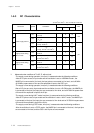
Crystal frequency f
xt al 1
V
DD
= 2.5 V to 3.6 V 1.0 20.0 MHz
External capasitors
C
11
47
pF
C
12
47
Internal feedback resistor R
F10
V
DD
= 3.3 V 1000 k
Ω
Crystal frequency f
xt al 2
V
DD
=1.8 V to 3.6 V 32.768 kHz
External capasitors
C
21
22
pF
C
22
22
6.0 M
Ω
Internal feedback resistor R
F20
V
DD
=3.3 V
Parameter Symbol Conditions Unit