


III - 47
Chapter 3 Interrupts
External Interrupts
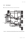
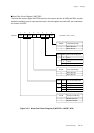
3-3-4 Programmable Active Edge Interrupt
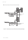
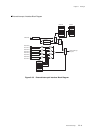
■Programmable Active Edge Interrupts (External interrupts 0 to 4)
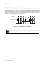
Through register settings, external interrupts 0 to 5 can generate interrupt at the selected edge either
rising or falling edge.
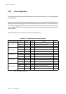
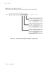
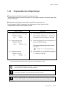
■Programmable Active Edge Interrupt Setup Example (External interrupt 0 to 4)
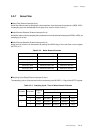
External interrupt 4 (IRQ4) is generated at the rising edge of the input signal from P24.
The table below provides a setup example for IRQ4.
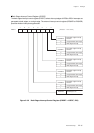
(1) Set the REDG4 flag of the external interrupt 4
control register (IRQ4ICR) to "1" to specify the
rising edge as the active edge for interrupts.
(2) Set the interrupt priority level in the IRQ4LV1-0
flag of the IRQ4ICR register.
If the interrupt request flag has been already
set, clear it.
[ Chapter 3. 3-1-4 Interrupt flag setup ]
(3) Set the IRQ4IE flag of the IRQ4ICR register to
"1" to enable the interrupt.
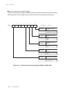
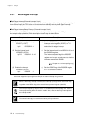
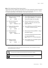
Setup Procedure
(1) Specify the interrupt active edge.
IRQ4ICR (x'3FE6')
bp5 : REDG4 = 1
(2) Set the interrupt level.
IRQ4ICR (x'3FE6')
bp7-6 : IRQ4LV1-0= 10
(3) Enable the interrupt.
IRQ4ICR (x'3FE6')
bp1 : IRQ4IE = 1
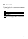
Description
External interrupt 4 is generated at the rising edge of the input signal from P24.
The Interrupt request flag can be set to "1" at switching the interrupt edge, so specify the
interrupt active edge before the interrupt permission.
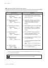
The external interrupt pin is recommended to be pull-up in advance.
When the programmable active edge interrupt is specified for external interrupt 0 to 4 (IRQ0
to IRQ4), set the EDGSELn flag of the both edge interrupt control register (EDGDT) to "0".