


Chapter 6 8-bit Timers
VI - 6
Control Registers
6-2 Control Registers
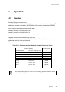
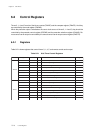
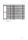
Table 6-2-1 8-bit Timer Control Registers
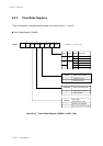
6-2-1 Registers
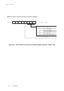
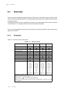
Table 6-2-1 shows registers that control timers 0, 1, 4, 5 and remote control carrier output
When the prescaler output is selected as the count clock source of timers 0, 1 4 and 5, they should be
controlled by the prescaler control register (PSCMD) and the prescaler selection register (CKnMD). Re-
mote control carrier output is controlled by the remote control carrier output control register (RMCTR).
Timers 0, 1, 4 and 5 consist of the binary counter (TMnBC) and the compare register (TMnOC). And they
are controlled by the mode register (TMnMD).
Register Address R/W Function Page
Ti mer 0
TM0BC x'03F50' R Timer 0 binary counter
VI-9
TM0OC x'03F52' R/W Timer 0 compare register
VI-8
TM0MD x'03F54' R/W Timer 0 mode register
VI-10
CK0MD x'03F56' R/W Timer 0 prescaler selection register
V-7
PSCMD x'03F6F' R/W Prescaler control register
V-6
TM0ICR x'03FE9' R/W Timer 0 interrupt control register
III-22
P1OMD x'03F2F' R/W Port 1 output mode register
IV-14
P1DIR x'03F31' R/W Port 1 direction control register
IV-13
Ti mer 1
TM1BC x'03F51' R Timer 1 binary counter
VI-9
TM1OC x'03F53' R/W Timer 1 compare register
VI-8
TM1MD x'03F55' R/W Timer 1 mode register
VI-11
CK1MD x'03F57' R/W Timer 1 prescaler selection register
V-7
PSCMD x'03F6F' R/W Prescaler control register
V-6
TM1ICR x'03FEA' R/W Timer 1 interrupt control register
III-23
P1OMD x'03F2F' R/W Port 1 output mode register
IV-14
P7DIR x'03F37' R/W Port 7 direction control register
IV-31