


Chapter 14 Automatic Transfer Controller
Operation
XIV - 20
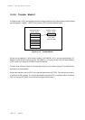
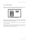
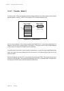
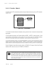
14-3-11 Transfer Mode 6
In transfer mode 6, ATC1 automatically transfers one byte of data two times every time an ATC1 activation
request occurs.
(1)
(2)
(3)
(4)
AT1MAP0
AT1MAP0 + 1
AT1MAP0 + 2
AT1MAP0 + 3
00000 - 3FFFF 03F00 - 03FFF
(Only lower
8 bits are valid)
AT1MAP1
Transfer mode 6 can be used to support continuous transmission/reception for serial inter-
face 3. Set memory pointer 1 to point to the serial transmission/reception shift register
(SCnTRB) and select serial interrupts as an ATC1 trigger factor. In this way, each time a
serial communication ends the MCU continuously reads the received data (first data byte
transfer) then writes the transmission data (second data byte transfer) up to 255 times,
entirely through the hardware.
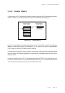
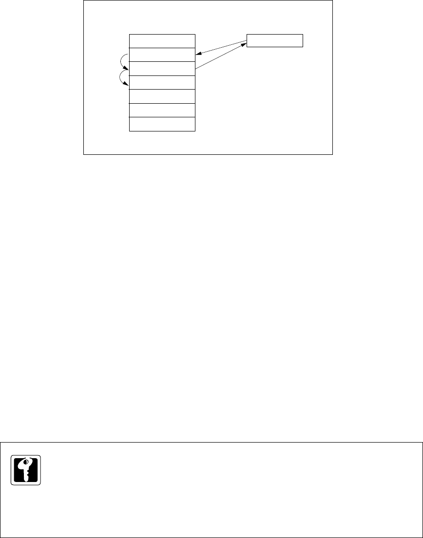
In this mode the transfer direction indicated by memory pointers 0 and 1 reverses for the second data
byte transfer.
In the first data byte transfer, the I/O space address (x'03F00' - x'03FFF') in memory pointer 1 is the
source address, and the address in memory pointer 0, for any memory space, is the destination address.
When the first data byte transfer ends, the address in memory pointer 0 increments by one.
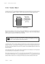
In the second data byte transfer, the incremented address in memory pointer 0 becomes the source
address, and the I/O space address (x'03F00' - x'03FFF') in memory pointer 1 becomes the destination
address. When the second data byte transfer ends, the address in memory pointer 0 increments again.
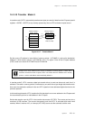
Set the I/O address in lower 8 bits of memory pointer 1 (AT1MAP1L). The upper 10 bits of the I/O space
address (x'03F') need not to be set in AT1MAP1H, AT1MAP1M.
Figure 14-3-8 Transfer Mode 6