


IX - 7
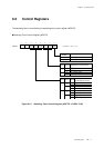
Chapter 9 Watchdog Timer
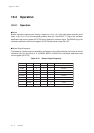
Operation
8
9-3-2 Setup Example
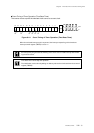
The watchdog timer detects errors. On the following example, the watchdog timer period is set to 2
18
×
system clock, the lowest value for watchdog timer clear is set to 2
9
× system clock.
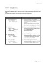
An example setup procedure, with a description of each step is shown below.
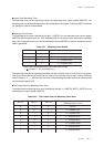
Main Routine Program (Watchdog Timer Constant Clear Setup Example)
(1) Clear the watchdog timer by the cycle from 2
9
× system clock up to 2
18
× system clock.
The watchdog timer clear should be inserted in
the main routine, with the same cycle, and to
be the set cycle.
The recommended instruction is the bit-set
(BSET), does not change value, for clear.
(1) Set the constant watchdog timer clear.
Writing to WDCTR (x'03F02')
(cf.) BSET (WDCTR) WDEN
(bp0 : WDEN = 1)
(1) Set the WDTS1-0 flag of the watchdog timer
control register (WDCTR) to "01" to select the
time-out period to 2
18
× system clock.
(2) Set the WDTC2-0 flag of the WDCTR register
to "010" to select the lowest value for clear to
2
9
× system clock.
(3) Set the WDEN flag of the WDCTR register to
start the watchdog timer operation.
(1) Set the time-out period.
WDCTR (x'03F02')
bp2-1 : WDTS1-0 = 01
(2) Set the lowest value for clear.
WDCTR (x'03F02')
bp5-3 : WDTC2-0 = 010
(3) Start the watchdog timer operation.
WDCTR (x'03F02')
bp0 : WDEN = 1
Setup Procedure
Description
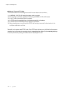
Initial Setup Program (Watchdog Timer Initial Setup Example)
The command of setting the WDEN flag to "1" should be done on the last step of the initial
setting. If the watchdog control register (WDCTR) is changed after starting the operation, the
watchdog interrupt may be generated depending on the setting of the lowest value for clear.
Setup Procedure
Description