


VII - 15
Chapter 7 16-bit Timer
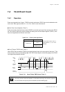
16-bit Event Count
N
0000 0001 0002 N-1
N
0000 0001
TM7IO
input
TM7EN
flag
Compare
register 1
Binary
counter
Interrupt
request flag
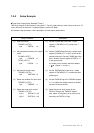
7-4 16-bit Event Count
7-4-1 Operation
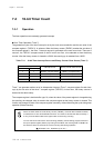
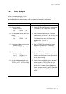
Event count operation has 2 types ; TM7IO input and synchronous TM7IO input can be selected as the
count clock. Each type can select 1/1, 1/2, 1/4 or 1/6 as a count clock source.
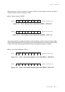
16-bit Event Count Operation (Timer 7)
Event count means that the binary counter (TM7BC) counts the input signal from external to the TM7IO
pin. If the value of the binary counter reaches the setting value of the compare register (TM7OC), inter-
rupts can be generated at the next count clock.
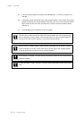
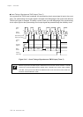
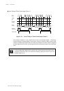
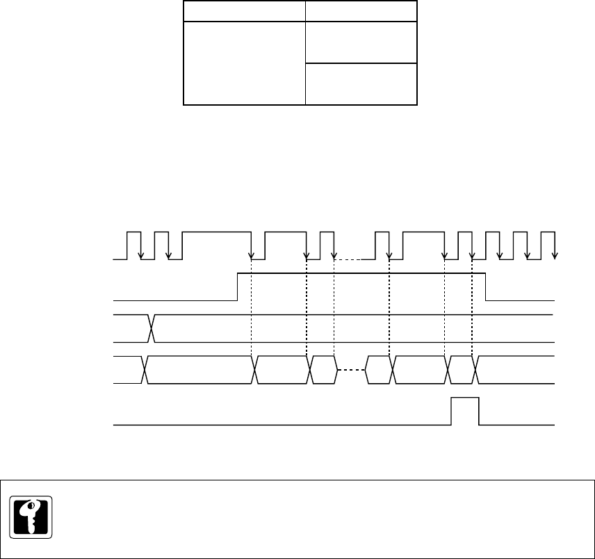
Count Timing of TM7IO Input (Timer 7)
When TM7IO input is selected, TM7IO input signal is directly input to the count clock of the timer 7. The
binary counter counts up at the falling edge of the TM7IO input signal or at the falling edge of the TM7IO
input signal that passed the divider.
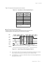
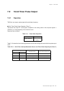
Table 7-4-1 Event Count Input Clock
Figure 7-4-1 Count Timing TM7IO Input (Timer 7)
As an actual count clock, a
signal divided 1, 2, 4, or 16 is
selected.
If the binary counter is read out at operation, incorrect data at counting up may be read. To prevent
this, use the event count by the synchronous TM7IO input as the following page.
Timer 7
TM7IO input
( P14 )
Synchronous
TM7IO input
Event input