Chapter 6 8-bit Timers
VI - 20
8-bit Event Count
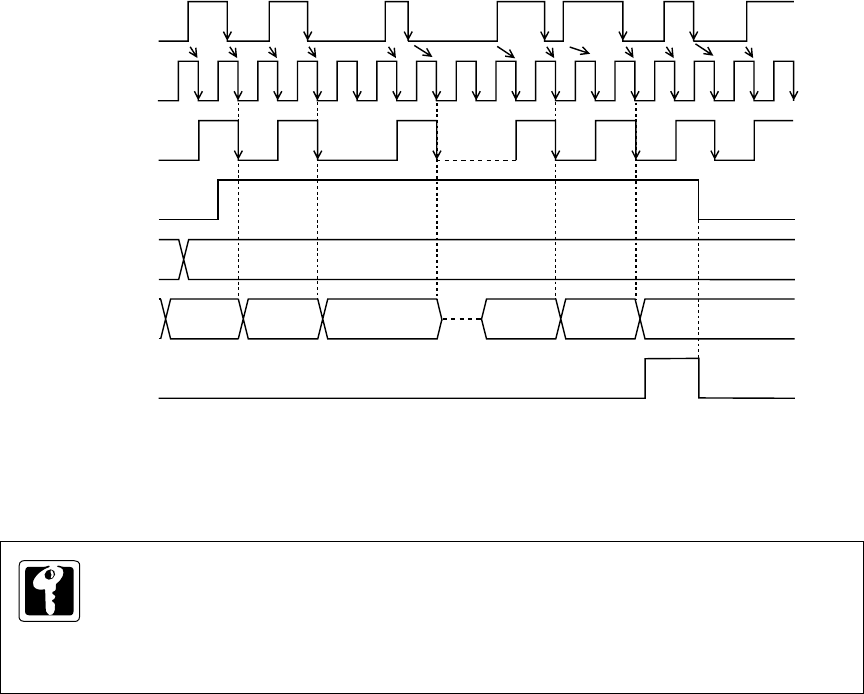
Count Timing of Synchronous TMnIO Input (Timers 0, 1, 4 and 5)
If the synchronous TMnIO input is selected, the synchronizing circuit output signal is input to the timer n
count clock. The synchronizing circuit output signal is changed at the falling edge of the system clock
after TMnIO input signal is changed.
M
N
00 01 02 N-1
N
00
TMnIO
input
TMnEN
flag
Compare
register
Binary
counter
Interrupt
request flag
Synchronizing
circuit output
(Count clock)
System
clock (fs)
Figure 6-4-2 Count Timing of Synchronous TMnIO Input (Timers 0, 1, 4 and 5)
When the synchronous TMnIO input is selected as the count clock source, the timer n
counter counts up in synchronization with system clock, therefore the correct value is always
read.
But, if the synchronous TMnIO is selected as the count clock source, CPU mode cannot
return from STOP/HALT mode.


