


II - 41
Chapter 2 CPU Basics
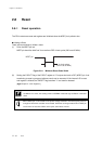
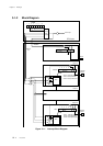
Reset
Control the Oscillation Stabilization Wait Time
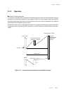
At recovering from STOP mode, the bit 3-2 (DLYS1, DLYS0) of the oscillation stabilization wait time
control register can be set to select the oscillation stabilization wait time from 2
14
, 2
10
, 2
6
, 2
2
x system
clock. The DLYCTR register is also used for controlling of buzzer functions.
[ Chapter 10 Buzzer ]
At releasing from reset, the oscillation stabilization wait time is fixed to "2
14
x system clock". System clock
is determined by the CPU mode control register (CPUM).
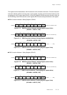
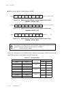
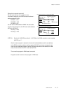
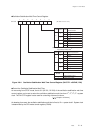
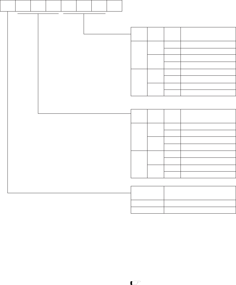
Oscillation Stabilization Wait Time Control Register
DLYS1DLYS2
0
0
DLYS0
0
1
0
1
1
fs/2
12
fs/2
10
fs/2
14
1
fs/2
8
01
24
567
3
(At reset: 0 0 0 0 0 0 0 -)
DLYCTR
-DLYS0
DLYS1DLYS2BUZS0
BUZS1
BUZS2
0
BUZS1
0
0
1
1
1
BUZS0
0
1
0
1
0
1
0
1
fosc/2
13
fosc/2
12
fosc/2
11
fosc/2
14
fx/2
3
fosc/2
10
fosc/2
9
fx/2
4
BUZOEBUZS2
BUZOE
0
1
0
0
1
0
1
fs/2
4
fs/2
2
fs/2
6
1
Reserved
Oscillation stabilization wait
period selection
Buzzer output
frequency selection
Note : After reset is released, the oscillation stabilization
wait period is fixed at fs/2
14
.
P06 buzzer output
P06 output selection
P06 port data output
Figure 2-8-4 Oscillation Stabilization Wait Time Control Register (DLYCTR : x'03F4D', R/W)