


Chapter 11 Serial Interface 0, 1
XI - 44
Operation
Frame Mode and Parity Check Setup
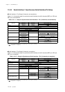
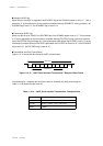
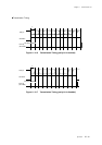
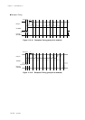
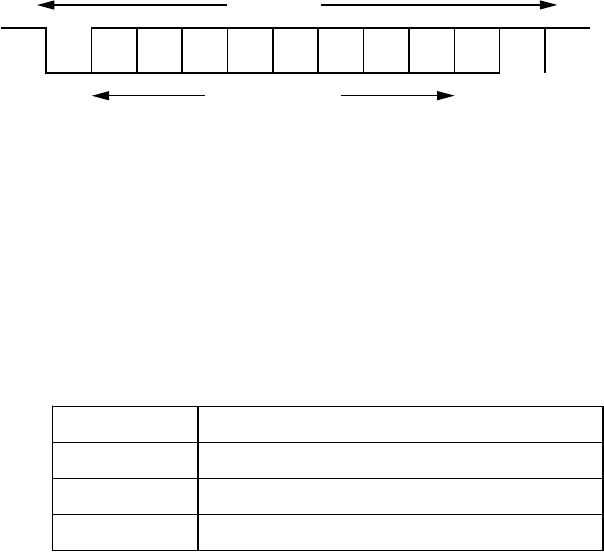
Figure 11-3-15 shows the data format at UART communication.
parity
bit
stop
bit
start
bit
character bits
1 data frame
Figure 11-3-15 UART Serial Interface Transmission / Reception Data Format
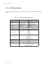
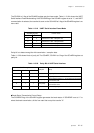
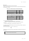
Table 11-3-18 UART Serial Interface Transmission / Reception Data
The transmission / reception data consists of start bit, character bit, parity bit and stop bit.
Table 11-3-18 shows its kinds to be set.
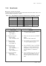
Reception BUSY flag
When the start condition is reagarded, the SCnRBSY flag of the SCnMD3 register is set to "1". That is
cleared to "0" by the generation of the reception complete interrupt SCnRIRQ. If, during reception, the
SCnSBIS flag is set to "0", the SCnRBSY flag is reset to "0".
Transmission BUSY flag
When any data is set to TXBUFn, the SCnTBSY flag of the SCnMD3 register is set to "1". That is cleared
to "0" by the generation of the transmission complete interrupt SCnTIRQ. During continuous communi-
cation the SCnTBSY flag is always set. If the transmission buffer empty flag SnTEMP is set to "0" as the
transmission complete interrupt SCnTIRQ is generated, the SCnTBSY is cleared to "0". If the SCnSBOS
flag is set to "0", the SCnTBSY flag is reset to "0".
Start bit 1 bit
Character bit 7, 8 bits
Parity bit fixed to 0, fixed to 1, even, odd, none
Stop bit 1, 2 bits