


XI - 3
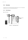
Chapter 11 Serial Interface 0, 1
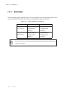
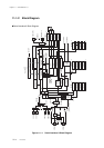
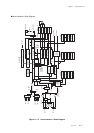
Overview
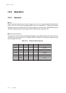
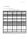
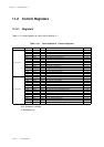
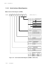
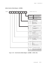
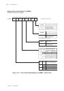
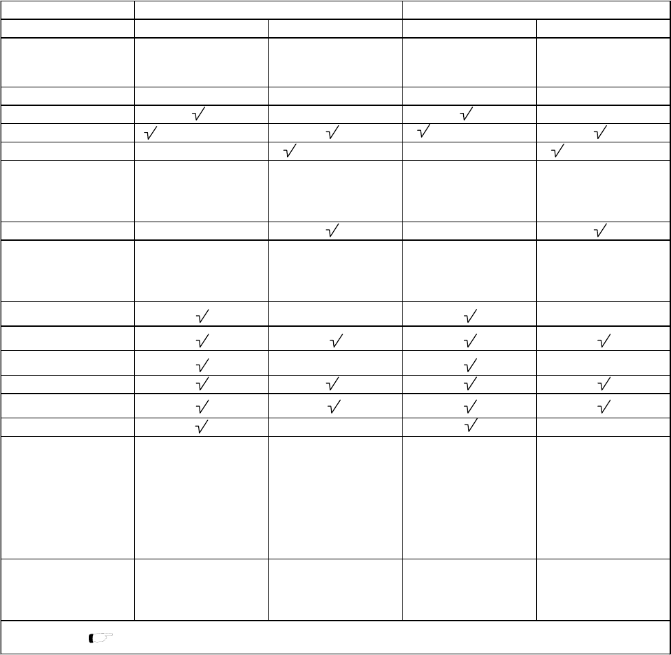
Table 11-1-1 Serial Interface 0, 1 Functions
11-1-1 Functions
Table 11-1-1 shows functions of serial interface 0, 1.
Communication style clock synchronous UART (duplex) clock synchronous UART (duplex)
SC0TIRQ
SC0TIRQ (on transmission
completion) SC1TIRQ
SC1TIRQ (on transmission
completion)
SC0RIRQ (on reception
completion)
SC1RIRQ (on reception
completion)
Used pins SBO0,SBI0,SBT0 TXD0,RXD0 SBO1,SBI1,SBT1 TXD1,RXD1
3 channels type - -
2 channels type (SBO0, SBT0) (SBO1, SBT1)
1 channel type - (TXD0) - 3 (TXD1)
7 bits + 1stop 7 bits + 1stop
7 bits + 2stops 7 bits + 2stops
8 bits + 1stop 8 bits + 1stop
8 bits + 2stops 8 bits + 2stops
Selection of parity bit - -
0 parity 0 parity
1 parity 1 parity
odd parity odd parity
even parity even parity
Selection of start condition
only ""enable start condition""
is available
only ""enable start condition""
is available
Specification of the first
transfer bit
Specification of input edge /
output edge
--
Continuous operation
Continuous operation (with
ATC1)
Internal clock 1/8 dividing only 1/8 dividing is available only 1/8 dividing is available
fosc/2 fosc/2 fosc/2 fosc/2
fosc/4 fosc/4 fosc/4 fosc/4
fosc/16 fosc/16 fosc/16 fosc/16
fosc/64 fosc/64 fosc/64 fosc/64
fs/2 fs/2 fs/2 fs/2
fs/4 fs/4 fs/4 fs/4
Timer 5 output Timer 5 output Timer 4 output Timer 4 output
External clock External clock
300 kbps 300 kbps
(standard 300 bps (standard 300 bps
to 38.4 kbps) to 38.4 kbps)
(timer 5 output) (timer 4 output)
fs : System clock [ Chapter 2 2-5. Clock Switching ]
-
2.5 MHz 2.5 MHz
Clock source
Maximum transfer rate
osc : Machine clock (High speed oscillation)
Interrupt
-
Serial interface 0 Serial interface 1
1 to 8 bits 1 to 8 bits
Specification of transfer bit
count / Frame selection
Parity bit control