


VI - 45
Chapter 6 8-bit Timers
Remote Control Carrier Output
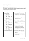
Setup Procedure Description
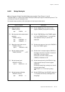
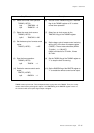
(6) Select the normal timer operation.
TM0MD (x'3F54')
bp4 : TM0PWM = 0
bp5 : TM0MOD = 0
(7) Select the count clock source.
TM0MD (x'3F54')
bp2-0 : TM0CK2-0 = 000
(8) Set the base cycle of remote control
carrier.
TM0OC (x'3F52') = x'6C'
(9) Start the timer operation.
TM0MD (x'3F54')
bp3 : TM0EN = 1
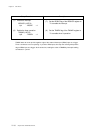
(10) Enable the remote control carrier
output.
RMCTR (x'3F6E')
bp3 : RMOEN = 1
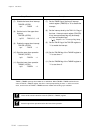
(6) Set both of the TM0MOD flag and TM0PWM
flag of the TM0MD register to "0" to select
normal timer operation.
(7) Select fosc to clock source by the
TM0CK2-0 flag of the TM0MD register.
(8) Set the base cycle of remote control carrier by
writing x'6C' to the timer 0 compare register
(TM0OC). The set value should be (8 MHz/
73.4 kHz) - 1 = 108(x'6C')
8 MHz is divided to be 73.4 kHz, 2 times
36.7 kHz.
(9) Set the TM0EN flag of the TM0MD register to
"1" to stop the timer 0 counting.
(10) Set the RMOEN flag of the RMCTR register to
"1" to enable the remote control carrier output.
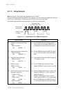
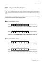
TM0BC counts up from x'00'. Timer 0 outputs the base cycle pulse set in TM0OC. Then, the 1/3 duty
remote control carrier pulse signal is output. If the RMOEN flag of the RMCTR register is set to "0",
the remote control carrier pulse signal output is stopped.